¶ Initial support in v1.0.128
¶ Features
- Full Torque control through Emtron Torque Estimation
- Cuts/Blips through Torque/RPM requests
¶ Connection
CANTCU CAN3 connects to one of the Emtron CANs
¶ Integration
¶ Communication Config
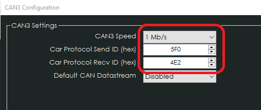
In CANTCU CAN3 Configuration, define the CAN-speed and freely definable Send/Receive IDs (Hex) for the CAN-messaging between CANTCU and Emtron.
In Emtron, the communication is realized via Custom Data Sets for both Tx and Rx. The Datasets are available to download on the bottom of this page in the Resources -section. Add both datasets to a free Data Set number (1-4), and configure the defined datasets on free Channels (1-6).
¶ Example configuration of the Rx Dataset loaded into Emtron Custom Rx Data Set 2 on CAN2 - Channel 1
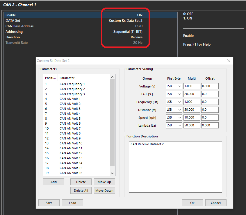
- DATA Set: The correct Custom Rx Dataset with parameters to be sent to CANTCU
- CAN Base Address: Can be freely chosen, but has to match CANTCU “Car Protocol Recv ID” (receive address in CANTCU). 1520(dec) = 0x5F0(hex)
- Addressing: Sequential (11-BIT)
- Direction: Receive
- Transmitt Rate: not adjustable
¶ Example configuration of the Tx Dataset loaded into Emtron Custom Tx Data Set 2 on CAN2 - Channel 2
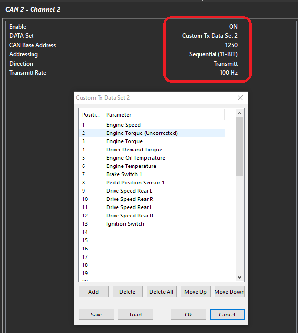
- DATA Set: The correct Custom Tx Dataset with parameters to be sent to CANTCU
- CAN Base Address: Can be freely chosen, but has to match CANTCU “Car Protocol Recv ID” (receive address in CANTCU). 1250(dec) = 0x4E2(hex)
- Addressing: Sequential (11-BIT)
- Direction: Transmitt
- Transmitt Rate: 100 Hz
¶ CANTCU Received Values
| Emtron CAN Tx | CANTCU Channel | Additional information |
| Engine Speed | Engine RPM | |
| Engine Torque (Uncorrected) | Engine Torque Uncorrected | Not shown in realtime values |
| Engine Torque | Engine Torque | |
| Driver Demand Torque | Requested Torque | Not shown in realtime values |
| Engine Oil Temperature | Engine Oil Temperature | |
| Engine Temperature | Engine Water Temperature | |
| Brake Switch | Brake Switch | Can be configured/wired directly to CANTCU also |
| Pedal Position Sensor 1 | TPS Value | |
| Drive Speed LF | WheelSpeed FL | Wheelspeed is mandatory for BMW DCT, not required for 8HP |
| Drive Speed RF | WheelSpeed FR | Wheelspeed is mandatory for BMW DCT, not required for 8HP |
| Drive Speed LR | WheelSpeed RL | Wheelspeed is mandatory for BMW DCT, not required for 8HP |
| Drive Speed RR | WheelSpeed RR | Wheelspeed is mandatory for BMW DCT, not required for 8HP |
¶ Emtron Received Values
| Emtron CAN Rx | CANTCU Channel | Emtron Channel | Conversion | CAN ID / Byte Offset |
|---|---|---|---|---|
| CAN Frequency 1 | Input Shaft Speed | Input Shaft Speed | 1.000V = 1000 RPM | Base / 0-1 |
| CAN Frequency 2 | Output Shaft Speed | Output Shaft Speed | 1.000V = 1000 RPM | Base / 2-3 |
| CAN Frequency 3 | TCU RPM Target | Turbo Speed 2 | 1.000V = 1000 RPM | Base / 4-5 |
| CAN AN Volt 13 | Torque Target | User Position 1 % | 1V = 0Nm, 1Nm = 0.001V | Base / 6-7 |
| CAN AN Volt 14 | Cut Request % | - | 0-1V = 0-100% | Base + 1 / 0-1 |
| CAN AN Volt 15 | Blip Request % | User Position 2 % | 0-1V = 0-100% | Base + 1 / 2-3 |
| CAN Lambda 5 | Shift Bit (1=Up, 2=Down) | - | 0/1/2V = -/cut/blip | Base + 1 / 4-5 |
| CAN Lambda 6 | Gearbox Gear | Gear XY Binary Calibration | 0-10V = -3 - 7 Gear | Base + 1 / 6-7 |
| CAN Lambda 7 | Paddle Up | - | 0/1V = 0/1 | Base + 2 / 0-1 |
| CAN Lambda 8 | Paddle Down | - | 0/1V = 0/1 | Base + 2 / 2-3 |
| CAN AN Volt 20 | Clutch/Converter Slip % | - | 0-1V = 0-100% | Base + 2 / 4-5 |
| CAN EGT 13 | Gearbox Drive Mod | - | 0/1/2/3V | Base + 2 / 6-7 |
| CAN EGT 14 | TCU Oil Temperature | Transmission Oil Temp | 1V = 0C, 1C = 0.010V | Base + 3 / 0-1 |
| CAN EGT 15 | DriveLogic Mode | - | 0/1/2/3V | Base + 3 / 2-3 |
| CAN Lambda 4 | Delayed Gear | - | 0-10V = -3 - 7 Gear | Base + 3 / 4-5 |
| CAN Speed | WheelSpeed | - | 0-5V = 0-500.0km/h | Base + 3 / 6-7 |
¶ Gear Detection
Gear Detection can be set various ways. In this example, it is set as XY table and is calibrated vs “CAN Lambda 6”. This can also be calibrated as a standard Gear Position Voltage. The Gear channel is a representation of target gear by CANTCU and not actual gear (Actual Gear is traansmitted/calculated on the “Delayed Gear” parameter). The system functions on this basis and calculates the ratio/slip and generates torque management subsequently.
| CAN Lambda 6 | -3 | -2 | -1 | 0 | 1 | 2 | 3 | 4 | 5 | 6 | 7 | 8 |
|---|---|---|---|---|---|---|---|---|---|---|---|---|
| Enum Result | Neutral | Reverse | Park | ERROR | 1 | 2 | 3 | 4 | 5 | 6 | 7 | 8 |
¶ Torque Model/Validation
The Emtron Torque Model must be calibrated and validated without question. This means the following critical set up areas must be addressed:
- Engine Details
- Displacement
- Compression Ratio (if Expansion Ratio is being used – Recommended)
- Trigger setup/Offset (critical for Ignition Base/Torque Model)
- Fuel
- Type
- Stoich
- Density
- Injectors (Flow, Deadtime, Linearization, etc)
- Sensor Calibrations
- Pressures (MAP/Boost/Fuel Pressure)
- Oil Temp (fitted and used to compensate Frictional Losses)
Tuning of various functions are furthermore required, in addition to basic tuning of the engine:
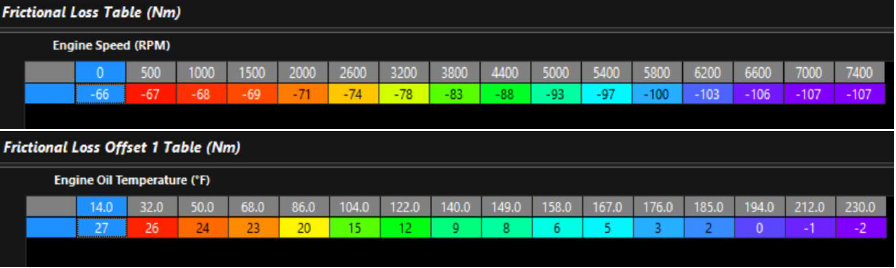
- Frictional Loss Tables must be set up and tuned.With a validated fuel model/air flow/minimal lambda error – this can be done by looking at Calculated Engine Torque values and “zeroing” the Engine Torque at different engine speeds. These values should be compensated in the Offset Tables most commonly by Engine Oil Temperature
2. Torque Limit Ignition Retard Scaling should be validated using a dyno. This will allow the ECU to calculate the torque reduction with ignition trims from the Ignition Base value (max ignition). Torque Reduction Ignition channels calculate constantly, so any Ignition Trims will validate torque reduction furthermore.
NOTE! This is a critical function that must be validated!
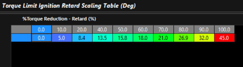
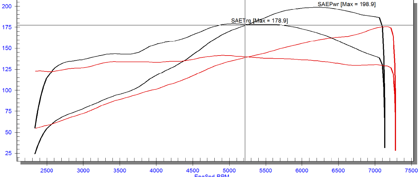
Different methods can be used to validate this. Steady state torque testing and applying Ignition Trims from Ignition Base (MBT), or simply creating an Ignition Retard Comp during a sweep can be done. Validating the amount of torque reduction (as a %) vs the ignition trims total is how you generate the ignition trim value vs % reduction.
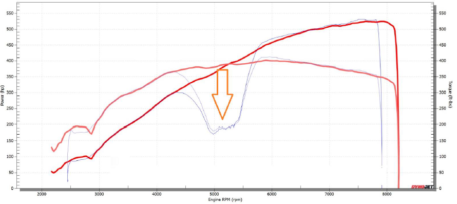
A 50% reduction of torque was achieved in the above example/test. Whatever ignition trims being used in that test need to be entered into the Retard Scaling Table
3. Torque Limit Cut Gain Table must also be validated by using a dyno. This will allow the ECU to calculate the torque reduction with cut%
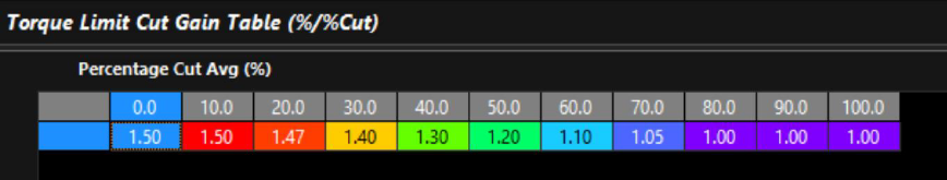
As with validating Torque Limit Ignition Retard, similarly you must introduce cuts into your test procedure to validate this. This can be done in several ways with clamping limiters, User Torque Limits, enabling functions that allow Limit %Cut values to be entered, etc. The above example is a good starting point, as when cut percents are low, the inertia of the engine will influence torque reductions cutting.
4. The Throttle Body Model must be fully configured and tuned. The size, Throttle Area Table, and Outflowing value must be validated.
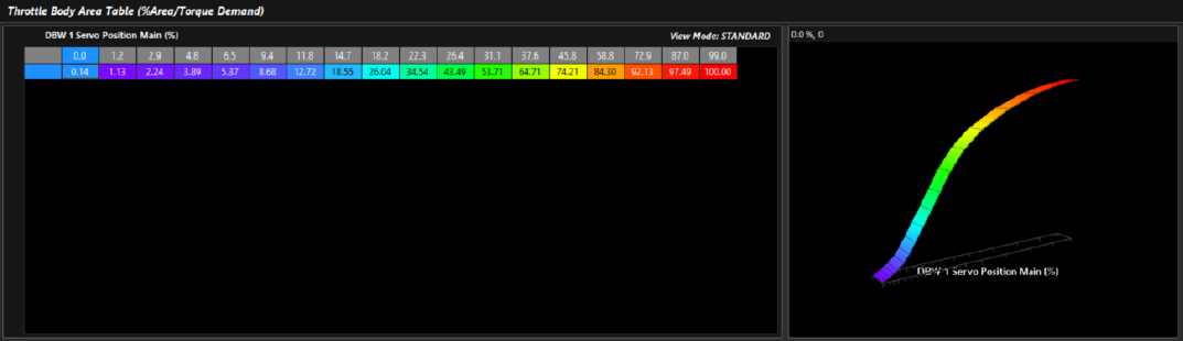
The Throttle Area can be validated in several ways. Validating the TMF Air Mass with minimal Lambda Target Error, or MAF is a good way to get started. Ultimately validating with Torque Reductions is the best way to validate Throttle Area.
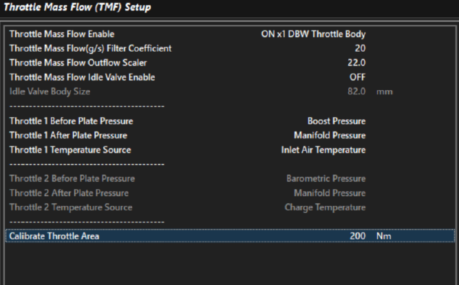
“Calibrate Throttle Area” will clamp the engine torque to this value and help get the system close testing. Outflow Scaler must also be adjusted. When the TMF calculation must rely on Virtual Air Mass (higher throttle pressure ratios) – it can then generate the correct throttle area for torque control. When the Throttle Pressure Ratio is 1, adjust the Throttle Mass Flow Outflow Scaler until the TMF Air Mass matches another validated source of Air Mass (such as SD, MAF, etc).
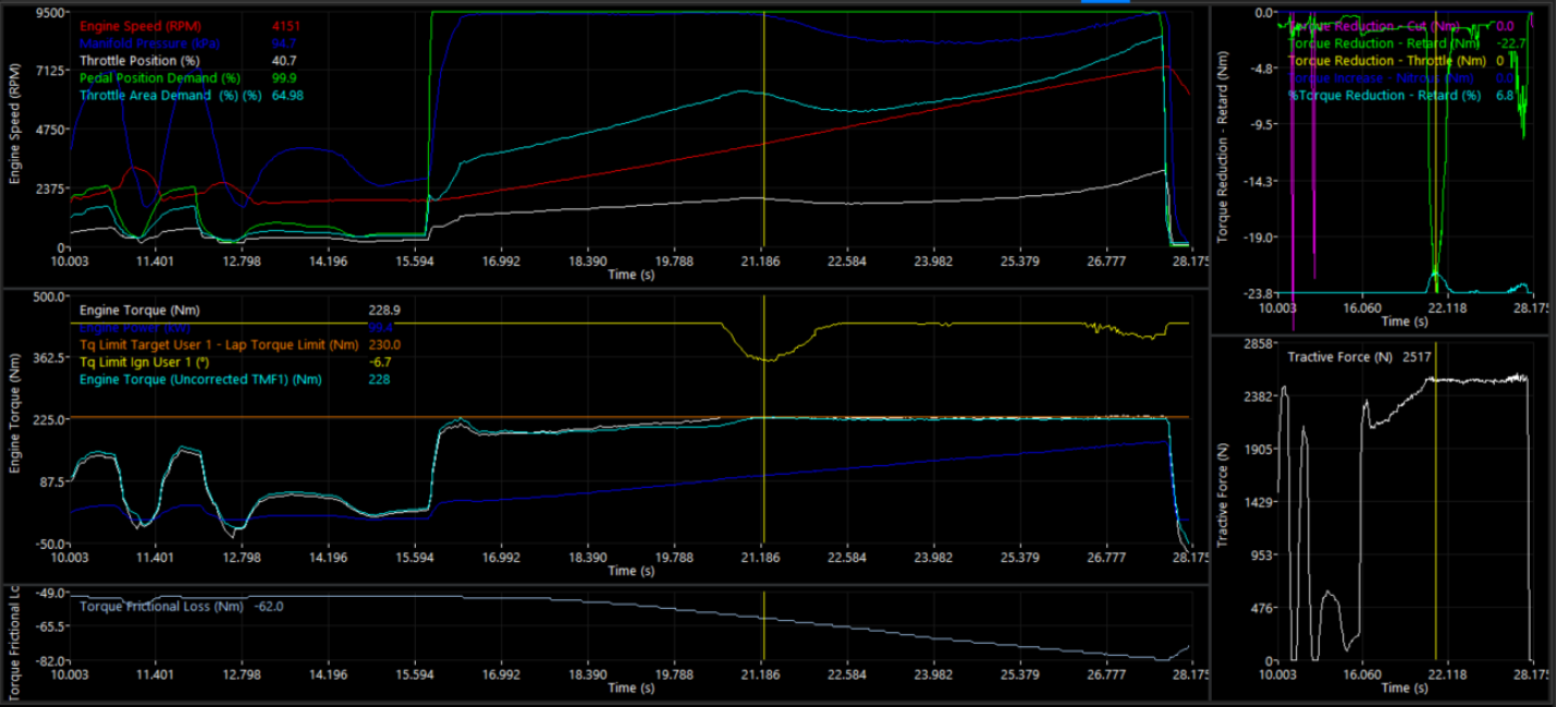
5. Validating Torque Reduction. To fully validate torque reduction is working correctly – employing “all” of the Torque Reduction Strategies for Torque Limiting is the best way to validate Torque Reduction. Setting a User Torque Limit, and then running the engine against this torque limit while measuring the values, is a good way to achieve this.
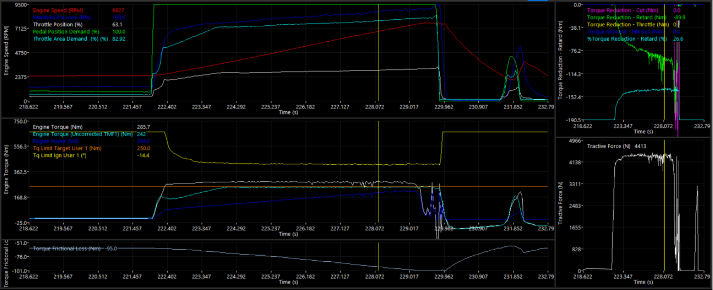
Looking at Tq Limit Runtimes (Tq Limit Ign, Tq Limit Cutting) can also help validate the Throttle Area. Above, a Tq Limit Target User 1 of 250nm is being enforced. The Tq Limit Ign User 1 is working excessively/constantly.
note the the reduction in torque% in the top left – Torque Reduction – Retard (Nm). This is validating there is too much throttle position for the Throttle Area Demand for the Tq Limit.
Correct the Throttle Area in the Throttle Area Table by moving the Throttle Area Demand value to a lower throttle position:
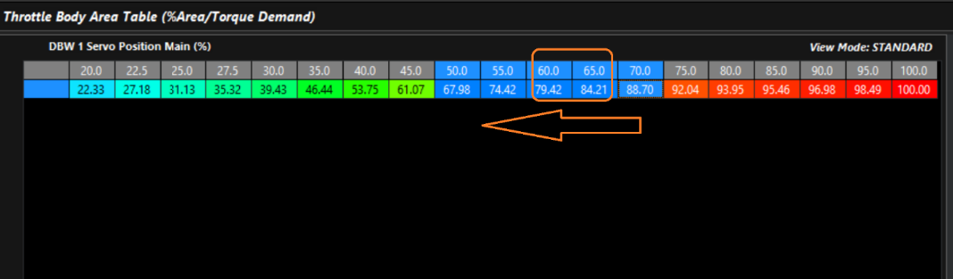
Increasing the Throttle Area Demand at lower throttle positions is how you achieve this
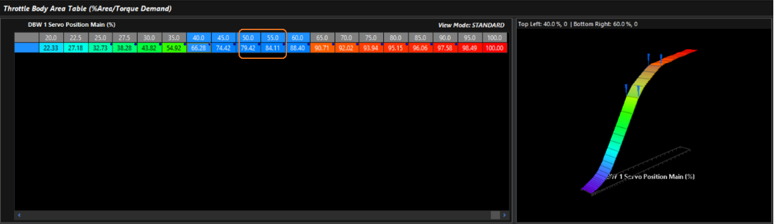
There are other methods to adjust the throttle area, such as using Calculated Channels to generate new Throttle Area values, however quickly shifting, and shaping the Throttle Area Table will yield quick results.
An example of a test where all Strats are working properly together.
¶ CANTCU Torque Limit Setup
A User Torque Limit is used for the CANFormance system to dictate torque management to the ECU.
1. User Torque Limits have base conditions, and a User Function must enable them.
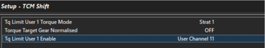
The routine begins with “User Output 11” in the example calibration.
User Output 11 (virtual) is used to trigger the Torque Limit. The example is simple, and it just looks at the CANTCU shift bit, and if it’s upshifting or downshifting (above 1) to initiate the torque limit. These options can be simplified/or made more complicated to suit the needs of the application.
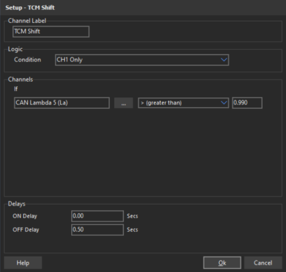
Base Conditions – Drive Speed and/any other condition can be added to initiate the function.
NOTE! the off delay to prevent the torque control flipping on/off in the event the CANTCU request is changing rapidly.
2. Torque Target. User Torque Limit 1 is configured to enforce torque limits dictated by CANTCU torque requests.
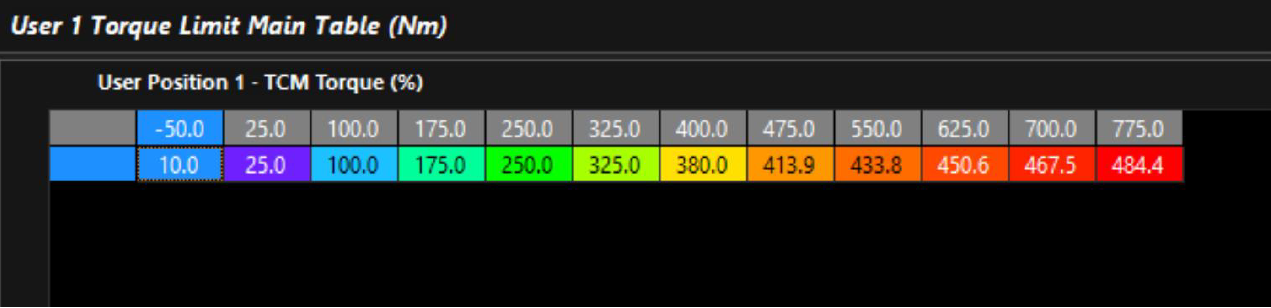
The main table follows the calculated channel as an axis TCM Torque (CANTCU input). The entered value is the torque target when the Torque Limit is active. The table can be manipulated/bent as needed/desired. In the above example, torque is being reduced at higher TCM Torque Requests.
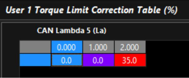
The Torque Limit Correction table can be used to further manipulate the Torque Limit Target. In the example, it’s being used to allow more target torque during Downshift Bit (+35%)
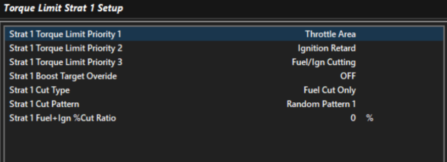
3. Torque Strategy. The User Torque 1 limit is following Torque Limit Strat 1. Here you can dictate how the Torque Limit is achieved and will behave, and with what priorities.
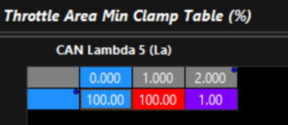
The Throttle Area Min Clamp table is arranged in a specific manner in the example calibration as a base. The strategy is preventing the Priority 1 from clamping the throttle at all during Upshift Bit (1.000), to force it to drop to Priority 2 (Ignition Retard). This is like OE strategy to provide “fast shift”.
When Downshift Bit is active, the Torque Strategy will allow clamping of the throttle to 1.00% area to control torque with all 3 strategies.
The Ignition Retard Clamp table is arranged in a similar manner. The strategy is like Throttle, allowing a different “Max” retard during different shifting bits from CANTCU (Up/Down).
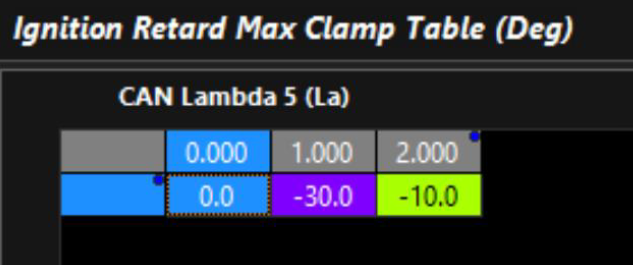
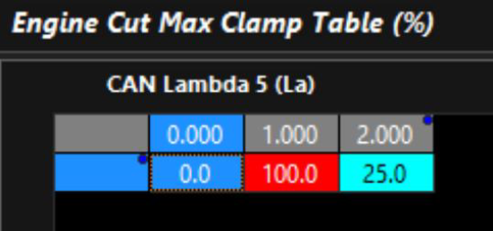
Finally, the Engine Cut Max Clamp table.
¶ Shifting
Shifting with DCT/Automatic gearbox controlling torque management requires a totally different state of mind when it comes to “normal motorsport sequential” ECU shifting strategy.
The TCM is what controls the shifting, routine, and therefore the engine almost completely.
This is completely the opposite of how a “normal” motorsport gearbox would be controlled with a typical Gearshift/Gear cutting system. It’s the main reason the Emtron Torque Model is a key component to being configured properly, and when configured properly works so well and comparable/better than the OEM even.
With all of the above set up, shifting is quite straightforward. Very little ECU configuration is needed to generate a shift strategy.
** The following is an example of shift strategy in the example calibration file
¶ Upshift
The upshifts are active when the shift bit changes to “1” (CAN Lambda 5 = 1), and the User Torque limit becomes active. It simply follows the torque target the TCM/CANTCU system is requesting during this time.
** The torque value of the requested torque is based on the actual engine torque values being valid – see Torque Model/Validation
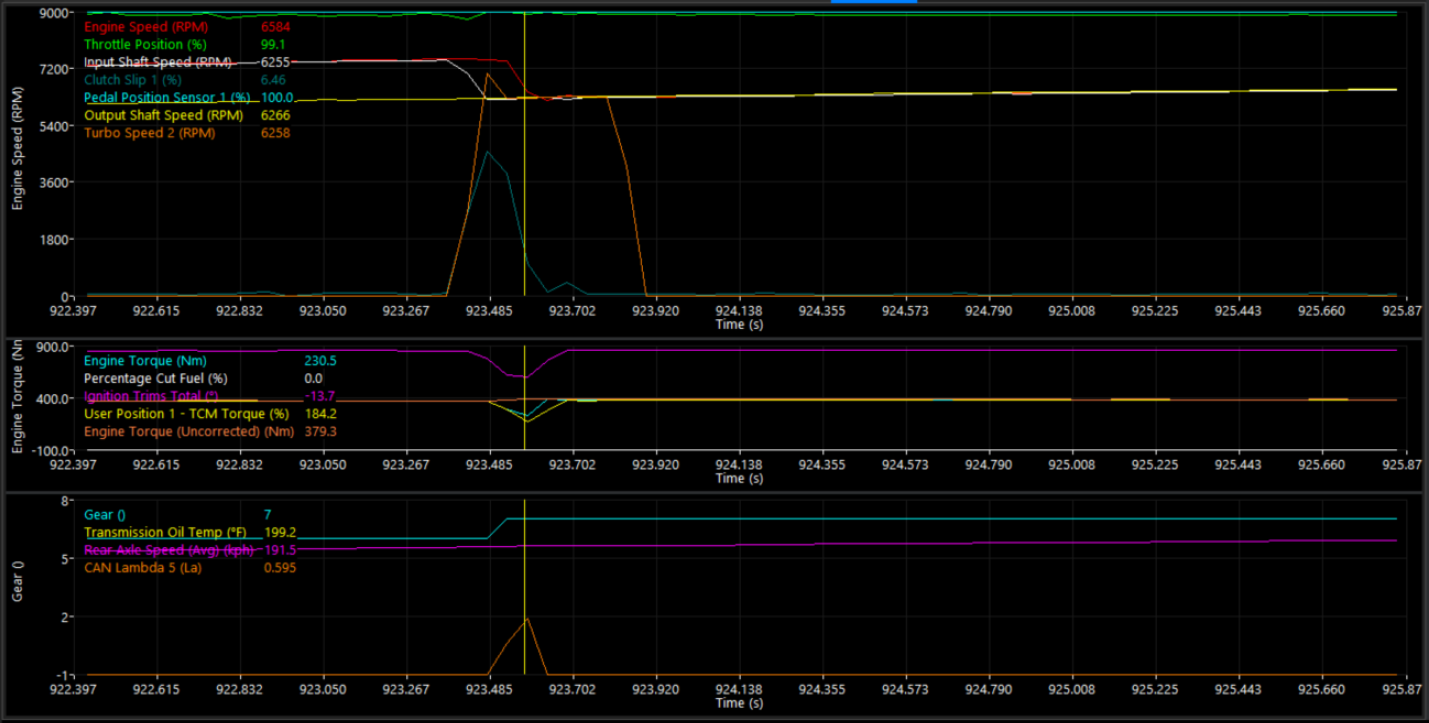
Observe Engine Torque following TCM Torque. Examples data logging speeds are slower than the shift happening.
¶ Downshift
Downshifting is similar, however follows shift bit “2” (CAN Lambda 5 = 2). The TCM generates target torque, so there is no need enable any “rev match” functions in the Emtron. Simply revving the engine into the torque limit will control the engine speed to the “Rev Match” target (Turbo Speed 2) automatically – ** with a fully tuned torque model.
To achieve “revving into the torque limit”, the CANTCU Blip Target is used to influence the axis of the Pedal Demand table in the example calibration.
A second Pedal Demand Table is selected when the Shift Bit is “2”
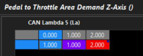
Which then allows the ECU to follow the axis of the Blip Position request from the CANTCU.
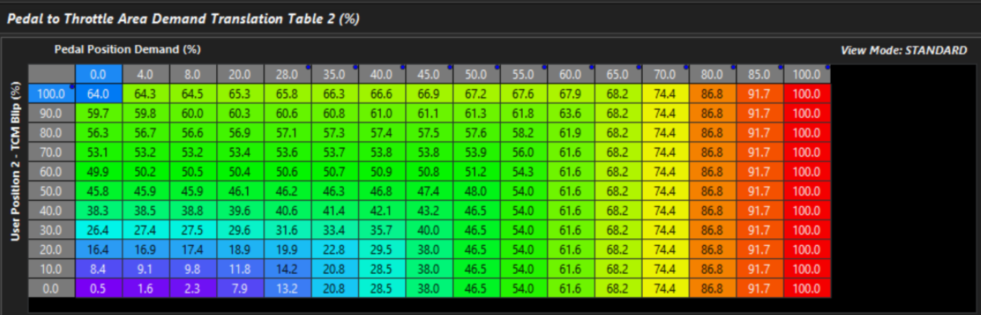
** Z axis enabling TCM Blip Position only when Shift Bit is 2 is critical
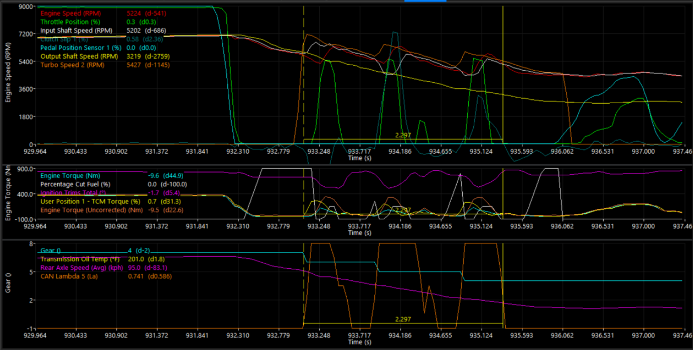
The above example is showing a track vehicle under full braking shifting down 3 gears in less than 3 seconds without any push, lockup, or driver issues.
Following the data, you can see Throttle Area Demand being driven into TCM Torque Limiting to control the engine speed to the TCM Target (Turbo Speed 2).
This is being performed without needless RPM limiting, cutting, or abuse – exactly the same way as OEM
¶ Tuning
The instructions and base file are simply a “base”. The end user can simplify this strategy or make it more complex as they desire.
Generally, most shifting tuning involves the following:
- Bending and adjusting the TCM Blip request into the Pedal Demand.
- Adjusting the torque target downshifting to ensure the downshift rev match is happening without being sluggish.
Each engine being used will have different transient behaviors and require slightly different settings.
¶ Resources
kv_sample_file_bosch68_tmf_idle_canformance.ecf