¶ Features
- Integrates as an “ECM Switch board”
- Uses values from “EMU stream” and a single custom Tx CAN frame
- Cut/retard based on CAN request
- Two different blip strategies (CANTCU/ECU controlled)
¶ Connection
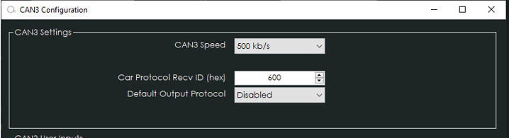
- CANTCU CAN3 is connected to ECUMaster CAN-bus.
- CAN Speed is configurable
- CAN2.0B, Standard 11bit identifiers
¶ Software Configuration
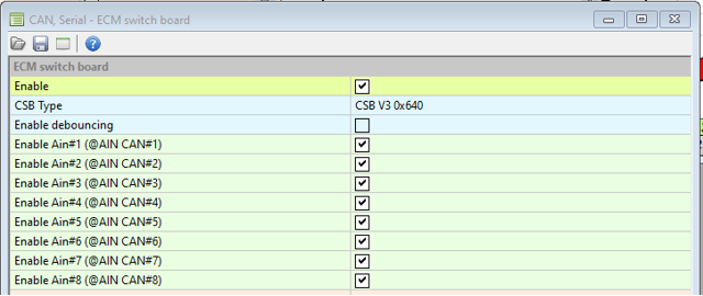
In ECUMaster, ECM Switch board of type CSB V3 0x640 needs to be enabled. CAN-bus speed/bit rate can be adjusted to suit project-specific requirements, default speed is 500kb/s.
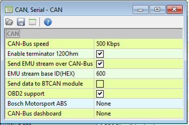
ECUMaster EMU Stream (CAN) needs to be enabled on the used CAN-bus. Base ID can be freely configured.
Inputs for cut/blip are sent from CANTCU as digital/analog channels
¶ Torque Factor (CANTCU)
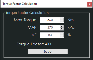
To achieve a somewhat realistic torque estimation, the ECU VE (fuel) table needs to be tuned and show real-world VE-values. For this torque estimation we use a Torque Factor. The torque factor is generated from engine running values taken from a single point of running (usually maximum measured torque on a dyno run). The values needed for calculation are listed below.
- Maximum Engine Torque (Nm)
- Manifold Absolute Pressure, MAP (kPa)
- Volumetric Efficiency, VE, Fuel Table (%)
Entering these values in the calculation window will generate a torque factor, which will be used as a baseline for torque calculations in the CANTCU.
¶ Blip Control (CANTCU)
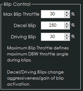
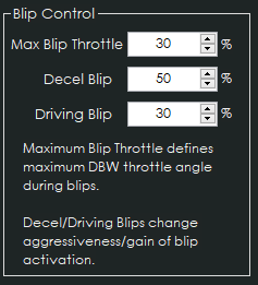
If CANTCU Blip Control strategy is used to control blips, the RT-value Throttle Blip is used as initial setpoint. Some extra adjustable parameters are available for fine tuning.
- Max Blip Throttle - Maximum DBW Throttle opening %
- Decel Blip - Sensitivity/Gain on deceleration/overrun
- Driving Blip - Sensitivity/Gain while TPS (Pedal) > 0 %
¶ Integration
NOTE!
All tuning should always be done by a professional in safe environment (track/dyno)
Before activating the blip function, it’s recommended to test downshifting and verify (realtime or logging) that the user table is behaving correctly during the blip. Starting values for tuning the blip should be low and gradually increased to avoid overrevving and undesired behavior/acceleration during the shift.
¶ ECUMaster Configuration
- ECM Switch board needs to be enabled, type CSB V3 0x640.
- EMU Stream needs to be enabled. Base ID can be changed, but it needs to match in both ECUMaster and CANTCU. (default value 0x600h)
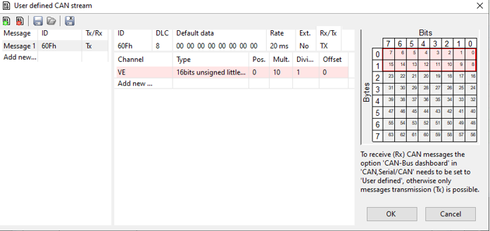
- Add a user defined CAN stream (Tx). Frame ID is calculated by adding 0x0Fh to the EMU Stream base ID (e.g. 0x600h + 0x0Fh = 0x60Fh). The CAN stream preset is available for download in the Resources chapter on the bottom of this page.
Available Realtime-values in CANTCU (sent from ECUMaster)
| Engine RPM |
| TPS Value (Pedal %) |
| Engine MAP |
| VSS Speed |
| Brake Switch |
| Coolant Temperature |
| Engine Oil Temperature |
Available Realtime-values in ECUMaster (sent from CANTCU)
| Gearbox Gear |
| Gearbox Mode |
| Gearbox Oil Temperature |
| Shiftcut (percentage and 0/1) |
| Blip (percentange and 0/1) |
| Clutch Slip % |
| Gearbox RPM Target |
Value Mapping CANTCU to ECUMaster
| ECM Channel | Type | Value Range | CANTCU variable | Scaling | Offset |
|
AIN1 |
UINT16 |
0-5000mV |
Cut % |
50mV / % |
|
|
AIN2 |
UINT16 |
0-5000mV |
Blip % |
50mV / % |
|
|
AIN3 |
UINT16 |
0-5000mV |
Clutch Slip % |
25mV / % |
2500mV = 0% |
|
AIN4 |
UINT16 |
0-5000mV |
RPM Target |
0.5mV / RPM |
|
|
AIN5 |
UINT16 |
0-5000mV |
TCU Oil Temperature |
10mV / °C |
1000mV = 0°C |
|
AIN6 |
UINT16 |
0-5000mV |
Gear Number |
100mV / Gear |
1000mV = "0" Gear |
|
AIN7 |
UINT16 |
0-5000mV |
Drive Mode |
1000mV/ Mode |
|
|
AIN8 |
UINT16 |
0-5000mV |
DriveLogic Mode |
1000mV/ Mode |
|
|
Switch 1 |
single bit |
0/1 |
Cut Active |
0/1 |
|
|
Switch 2 |
single bit |
0/1 |
Blip Active |
0/1 |
|
|
Switch 3 |
single bit |
0/1 |
|||
|
Switch 4 |
single bit |
0/1 |
|||
|
Switch 5 |
single bit |
0/1 |
|||
|
Switch 6 |
single bit |
0/1 |
|||
|
Switch 7 |
single bit |
0/1 |
|||
|
Switch 8 |
single bit |
0/1 |
¶ Configuring Inputs – Oil Temperature
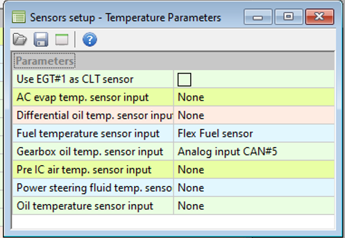
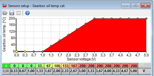
Oil Temperature is configured by selecting Analog input CAN#5 as Gearbox oil temp. sensor input in the Sensors -> Temperature menu structure. ECUMaster does not accept negative values, so minimum shown temperature is limited to 0°C.
¶ Configuring Inputs – Gearbox Gear
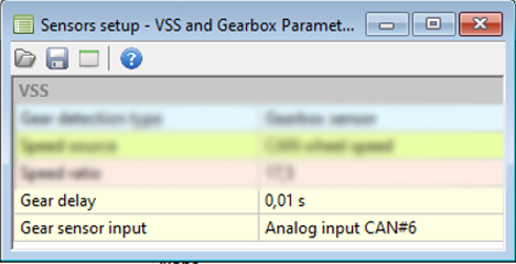
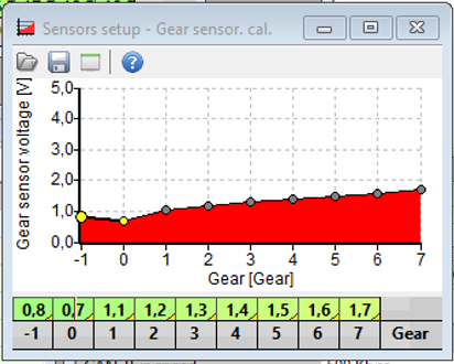
Gear number is configured by selecting Analog input CAN#6 as Gear sensor input in the Sensors -> VSS and Gearbox menu structure. Calibration steps are 100mV per gear. Gear 0 = Neutral, Gear -1 = Reverse. A maximum of seven forward gears can be defined.
¶ Tuning – Shiftcut
There are several different ways of configuring cuts. The way described here has been tested to work nicely in various applications. The strategy combines both cutting and retarding the ignition, and makes use of the analog and digital triggers sent from CANTCU.
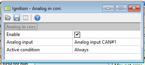
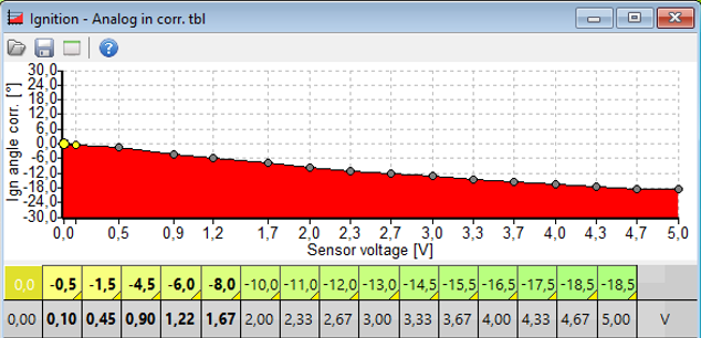
In Ignition -> Corrections an input and table can be configured for retarding ignition based on Analog input CAN#1.
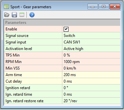
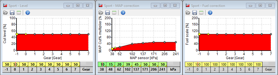
In Sport -> Gear Cut a CAN switch (Cut Active Indication 0/1) is defined to trigger functions and maps related to the Gear Cut function. The various parameters affecting the cut can then be adjusted until the desired functionality/shift characteristic is achieved.
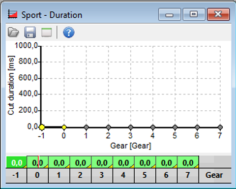
Note: Sport – Duration map shall be set at 0 ms
¶ Tuning – Throttle Blip
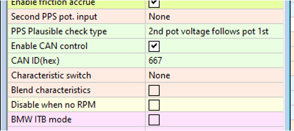
Throttle blips can be done either using various methods, like the Sport -function, a DBW Characteristic map blended in using the Blip % as a blend value, or directly through DBW Parameters as a CAN-request. It’s recommended to use one of the DBW options, as they offer the best flexibility for tuning. The CAN-request option is explained here.
By using direct control of the DBW throttle, the desired DBW opening % is directly requested and modulated by CANTCU during the blip. The function is enabled in DBW -> Parameters. CAN control should be activated, and the CAN ID used set to 0x667h. In CANTCU Configurator it is possible to adjust the sensitivity and max blip percentage.