¶ Initial support in v1.0.137
¶ Features
- Integrates as 4 consecutive Holley CAN I/O Modules on the Holley Standard CAN
- Freely selectable values to be used in the Holley software
- CAN speed static 1Mbps (Holley CAN requirement)
- Cut/Blip functionality
- Predefined values
- CANTCU AIN/DIN/DOUTs routed through to Holley (I/O Expansion)
NOTE! CANTCU uses VE values from Holley to estimate torque. If no VE is calculated in Holley (e.g. using Speed Density), you will need to use the Torque Map in CANTCU instead (v1.1 onwards).
¶ Integration
¶ Holley Receive Values
Below is a table of all values possible to route from CANTCU to Holley, and their respective addresses and scaling. It is not necessary to use all the values.
| Module # | Type | Number | CANTCU variable | Holley Type | Conversion |
|---|---|---|---|---|---|
| ID + 0 | Input | 1 | Cut Active | CAN GROUND | 0/1 |
| ID + 0 | Input | 2 | Blip Active | CAN GROUND | 0/1 |
| ID + 0 | Input | 3 | Cut 0-100% | CAN 5 VOLT | 0-5V = 0-100% |
| ID + 0 | Input | 4 | Blip 0-100% | CAN 5 VOLT | 0-5V = 0-100% |
| ID + 0 | Input | 5 | Target RPM | CAN 20 VOLT | 0-20V = 0-10000RPM |
| ID + 0 | - | 6 | RESERVED | - | - |
| ID + 0 | Input | 7 | Gearbox Gear | CAN 5 VOLT | 1V=1st Gear, 0.5V increments |
| ID + 0 | Input | 8 | TCU Oil Temperature | CAN 5 VOLT | 0-5V = -40C to 160C (-40F to 320F) |
| ID + 1 | Input | 1 | TCU Input RPM | CAN 20 VOLT | 0-20V = 0-10000RPM |
| ID + 1 | Input | 2 | TCU Output RPM | CAN 20 VOLT | 0-20V = 0-10000RPM |
| ID + 1 | Input | 3 | TQ Converter Slip | CAN 5 VOLT | 0-5V = 0-100% |
| ID + 1 | Input | 4 | Clutch Slip | CAN 5 VOLT | 0-5V = 0-100% |
| ID + 1 | Input | 5 | Delta RPM | CAN 20 VOLT | 0-20V = -999-9999RPM |
| ID + 1 | - | 6 | RESERVED | - | - |
| ID + 1 | Input | 7 | Gearbox Drive Mode | CAN 5 VOLT | 0-5V, 1V increments |
| ID + 1 | Input | 8 | Gearbox/car DriveLogic Mode | CAN 5 VOLT | 0-5V, 0.5V increments |
| ID + 2 | Input | 1 | DIN1 | CAN GROUND | 0/1 |
| ID + 2 | Input | 2 | DIN2 | CAN GROUND | 0/1 |
| ID + 2 | Input | 3 | DIN3 | CAN GROUND | 0/1 |
| ID + 2 | Input | 4 | DIN4 | CAN GROUND | 0/1 |
| ID + 2 | Input | 5 | AIN1 | CAN 5 VOLT | 0-5V |
| ID + 2 | Input | 6 | AIN2 | CAN 5 VOLT | 0-5V |
| ID + 2 | Input | 7 | AIN3 | CAN 5 VOLT | 0-5V |
| ID + 2 | Input | 8 | AIN4 | CAN 5 VOLT | 0-5V |
| ID + 3 | Output | 1 | DOUT1 | CAN GROUND | 0/1 |
| ID + 3 | Output | 2 | DOUT2 | CAN GROUND | 0/1 |
| ID + 3 | Output | 3 | DOUT3 | CAN GROUND | 0/1 |
| ID + 3 | Output | 4 | DOUT4 | CAN GROUND | 0/1 |
| ID + 3 | - | 5 | RESERVED | - | - |
| ID + 3 | - | 6 | RESERVED | - | - |
| ID + 3 | - | 7 | RESERVED | - | - |
| ID + 3 | - | 8 | RESERVED | - | - |
¶ Configuring Values to be received
In CANTCU, define a I/O Module ID. This ID will be used in Holley as the CAN ID for the value.
In Holley, define inputs based on your needs. Input types are listed in the Holley Receive Values table above.
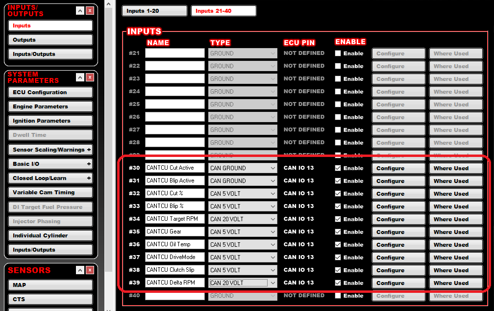
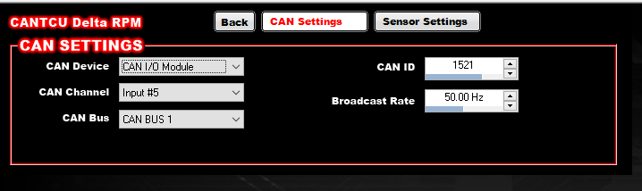
For every input, use the Configure-button to configure the input. For example, Input #30 “CANTCU Cut Active” below:
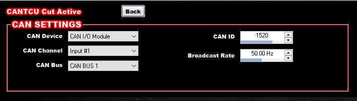
- CAN Device: CAN I/O Module
- CAN Channel: Channel listed in the Holley Receive Values table
- CAN Bus: The Holley CAN-bus CANTCU is physically wired to
- CAN ID: ID + offset listed in the Holley Receive Values table, based on the I/O Module ID input in CANTCU
- Broadcast Rate: 50.00 Hz
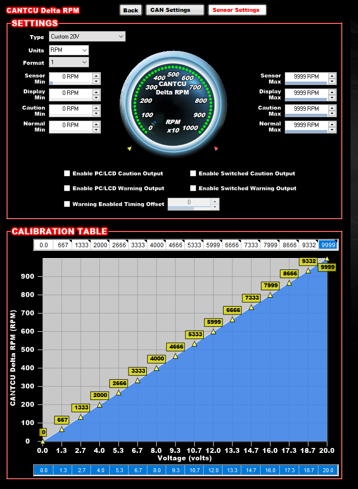
For voltage-based inputs, the configuration allows to scale the input value to a suitable value to be used in Holley. For example, Input #39 “CANTCU Delta RPM” is a 0-10000RPM value that's scaled to a 0-20V value through CAN, and needs to be rescaled back to 0-10000RPM in Holley. Note the CAN ID and Input # reflecting the specs listed in the Holley Receive Values table above.
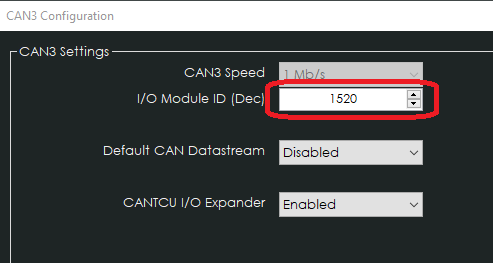
¶ CANTCU I/O Expander
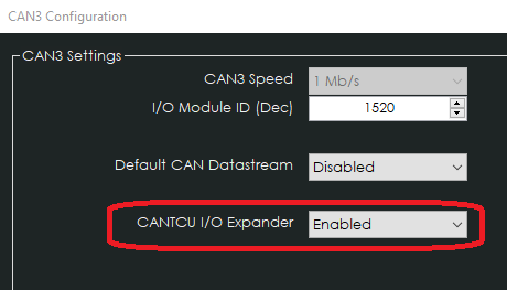
It's possible to use CANTCU Inputs (DIN/AIN) and Outputs (DOUT) directly in Holley through an extra I/O module (ID + 3).
This functionality is separately enabled in CANTCU CAN3 Configuration.
In Holley, the CANTCU AIN/DIN inputs are configured identically to the other values explained earlier. Controlling the CANTCU DOUTs (Digital Outputs) through Holley are configured in Holley Output Configuration.
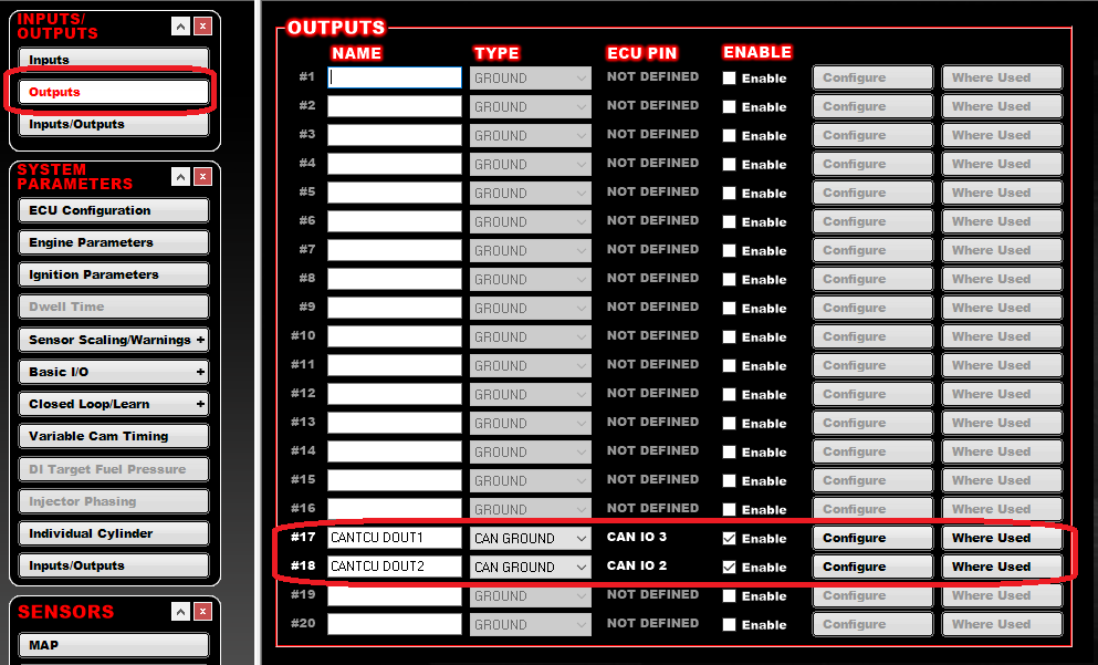
For every output, use the Configure-button to configure the output. For example, Input #17 “CANTCU DOUT1” below:
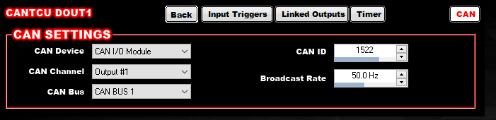
- CAN Device: CAN I/O Module
- CAN Channel: The physical Output on the CANTCU you want to use (1-4)
- CAN Bus: The Holley CAN-bus CANTCU is physically wired to
- CAN ID: ID + offset listed in the Holley Receive Values table, based on the I/O Module ID input in CANTCU
- Broadcast Rate: 50.00 Hz
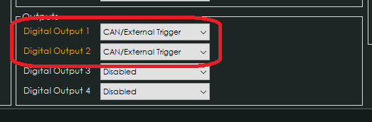
In CANTCU, enable the corresponding Digital Outputs as CAN/External Triggers to allow the command from Holley to be routed through to the CANTCU DOUT.
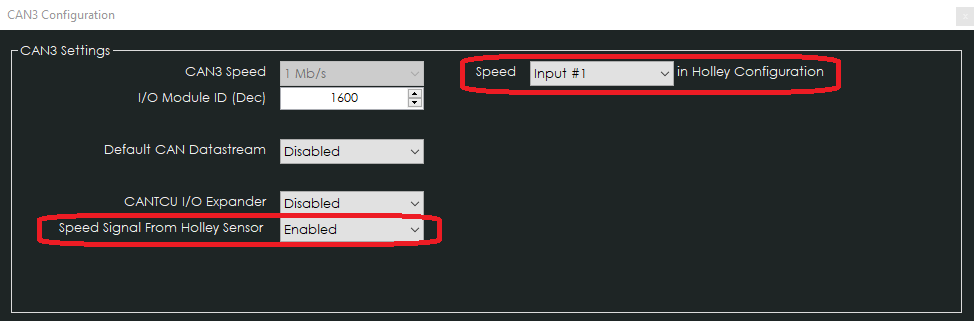
¶ Speed input from Holley into CANTCU
NOTE! A speed input/signal to CANTCU is mandatory only on DCT transmissions. 8HPs can use Simulated WheelSpeed in CANTCU.
This functionality is separately enabled in CANTCU CAN3 Configuration.
→ Enable "Speed Signal From Holley Sensor"
→ Select the correct Input # to which the sensor is physically wired in Holley.
Speed values are automatically multiplied by 1.6 to get km/h from mph (that Holley is broadcasting).