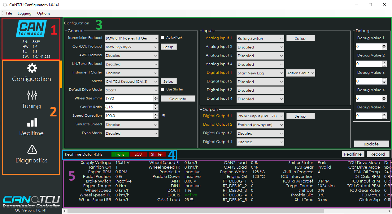
¶ User Interface
- Unit information and connection status (CANformance logo grey when disconnected, blue when connected)
- Menu buttons that define which section is being shown in main window (3)
- Main window
- Indicators
- Realtime values
¶ Graph & Gauges
In the realtime-section of the software, you can show realtime graphs and/or gauges to visualize running values from the transmission, ECU and CANTCU.
- Selection of graph values to be shown is done by clicking on the desired realtime value (marked in red below)
- Selection of gauge value is changed by clicking at the orange gauge indicator
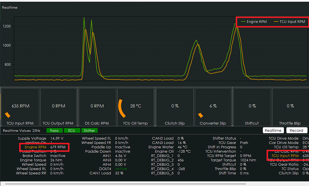
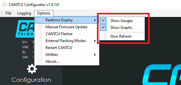
It's possible to select either gauges or graphs, or both, to be displayed. A slow refresh option is also available for older/slow computers.
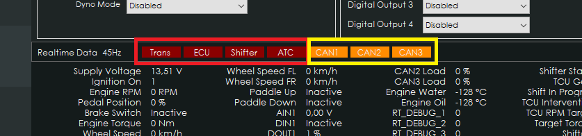
¶ Indicators
Device indicators (shown in red) indicate if the device is connected (Green) or not (Red).
CAN-bus indicators (shown in yellow) appear as orange if there is a physical issue with the corresponding CAN-bus. A physical issue could be wrong CAN-bus speed or a wiring issue etc. The CAN-bus indicators stay hidden if no issues are found.
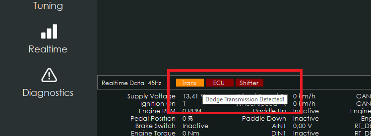
¶ Detection of unsupported transmissions
If an unsupported transmission is connected, it might be detected in CANTCU by an orange-colored transmission indicator. Hovering mouse over the indicator will show which transmission is detected. Note that not all unsupported transmissions are automatically detected. An unsupported transmission can be converted for CANTCU usage via bench flash, see Supported Transmissions.
Currently detected: Dodge/BMW E-Series/Jaguar/Land Rover 1stGen 8HPs.
¶ Realtime Values
| Name | Unit | Description | Source |
|---|---|---|---|
| Supply Voltage | Volt | Supply Voltage at VIN | Internal |
| Engine RPM | RPM | Engine RPM | Car |
| TPS Value | % | Throttle value in percent | Car |
| Engine Torque | Nm | Actual Engine Torque | Car |
| Brake Switch | 0/1 | Brake Switch Input State | Car/DIN |
| Wheel Speed | km/h | Average Wheel Speed | Car |
| Wheel Speed HL | km/h | Wheel Speed Rear Left | Car |
| Wheel Speed HR | km/h | Wheel Speed Rear Right | Car |
| Wheel Speed VL | km/h | Wheel Speed Front Left | Car |
| Wheel Speed VR | km/h | Wheel Speed Front Right | Car |
| Paddle Up | 0/1 | Paddle Up + State | Car/DIN |
| Paddle Down | 0/1 | Paddle Down - State | Car/DIN |
| AIN1 | V | Analog Input 1 Voltage | Internal |
| AIN2 | V | Analog Input 2 Voltage | Internal |
| AIN3 | V | Analog Input 3 Voltage | Internal |
| AIN4 | V | Analog Input 4 Voltage | Internal |
| DIN1 | 0/1 | Digital Input 1 State | Internal |
| DIN2 | 0/1 | Digital Input 2 State | Internal |
| DIN3 | 0/1 | Digital Input 3 State | Internal |
| DIN4 | 0/1 | Digital Input 4 State | Internal |
| DOUT1 | 0/1 | Digital Output 1 State | Internal |
| DOUT2 | 0/1 | Digital Output 2 State | Internal |
| DOUT3 | 0/1 | Digital Output 3 State | Internal |
| DOUT4 | 0/1 | Digital Output 4 State | Internal |
| CAN1 Load | % | Load on CAN-bus | Internal |
| CAN2 Load | % | Load on CAN-bus | Internal |
| CAN3 Load | % | Load on CAN-bus | Internal |
| Engine MAP | kPa | Engine MAP | Car |
| Shifter Status | Shifter position | Transmission | |
| Shift In Progress | 0/1 | Transmission | |
| Shift Requested | 0/1/2 | Indication of no/down/upshift | Transmission |
| TCU Gear | Current Gear | Transmission | |
| TCU Oil Temp | °C | Transmission Oil Temperature | Transmission |
| TCU DL Mode | Drivelogic/Selector Mode | Transmission | |
| DS Calc RPM | RPM | Calculated Driveshaft RPM | Internal |
| TCU Input RPM | RPM | Transmission Input RPM | Transmission |
| TCU Output RPM | RPM | Transmission Output RPM | Transmission |
| TCU Gear Ratio | Transmission Gear Ratio | Transmission | |
| TCU Intervention | 0/1/2 | Request None/Blip/Cut | Transmission |
| Target Torque | Nm | Desired Torque | Transmission |
| Shift Time | ms | Last Shift Time in ms | Transmission |
| TCU Drive Mode | Transmission | ||
| Shiftcut | % | Percentage of cut request | Transmission |
| Throttle Blip | % | Percentage of blip request | Transmission |
| TC Status | 0/1/2 | Torque Converter Open/Slipping/Locked | Transmission |
| Clutch Slip | % | Clutch Slip percentage | Transmission |
| Converter Slip | % | Torque Converter Slip percentage | Transmission |
| LC Enabled | 0/1 | Launch Control Enabled State | Car/DIN |
| LC Active | 0/1 | Launch Control Active State | Transmission |