¶ Initial support in v1.0.0
¶ Features
- 100% OEM torque-based control resulting in real OEM drivability
- No tuning needed
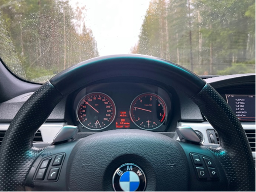
- Gear indicator in instrument cluster (including D/S/M-modes)
- Fully working cruise control (Standard/Braking/ACC)
- Drive Mode selection by DTC-button
¶ Connection
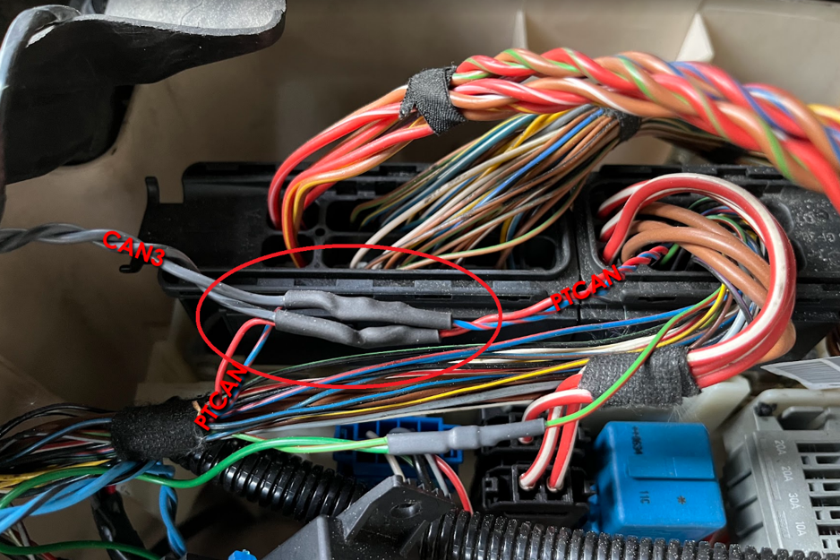
CANTCU CAN3 is connected to PTCAN on the car side. PTCAN-wires can be found in multiple locations, and they are usually colored blue and blue/red.
¶ Coding / Programming Requirements
Car needs to be fully coded as an automatic (S205A in VO/FA) and the DME/DDE programmed using automatic transmission software to support torque interventions.
Additionally, the CAS unit needs specific coding to allow detection of P/N via CAN for fault-free operation:
- CAS:
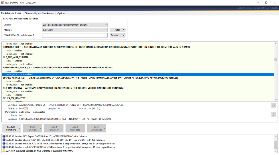
AUSWERTUNG_P_HW→nicht_aktiv - CAS:
ABZUGSPERRE_PLOCK_C6→nicht_aktiv - CAS, E65 only:
ANLASSERSPERRE_HW→nicht_aktiv
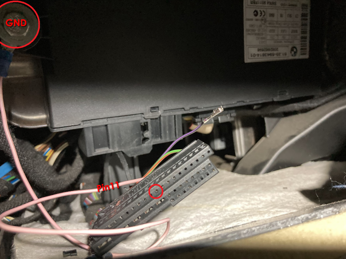
In some models CAS will throw a fault code regarding PLOCK. This is fixed by adding an extra ground wire on CAS pin 11
In some models, the RPM needle behavior will be erratic. Fixed by changing the value of DZM_DISP_RPM in KOMBI.
¶ Limitations
E6x instrument clusters are not able to show higher gears than 7th.
¶ Instrument cluster
On specific models with the “HIGH KOMBI” (instrument cluster) installed, there is a possibility to use “Motorsport”-coding which activates big gear numbers (1-7) and a drivelogic bar display (1-6) which can be configured through CANTCU to indicate drive modes, temperatures, etc. Full description on the E6789x cluster page.

¶ Torque Correction
Particularly on tuned N54 cars (MSD80/81/MEVD17), the torque value sent by the ECU/DME can be too low, resulting in spongy/slow shifts. The torque correction factor can be used to adjust this torque value if needed (percentage correction). On diesel engines (DDE6/7) an inaccurate value can only be caused by a bad tune. On stock engines the value is always accurate. The torque correction factor is just a band-aid meant to be used as last resort. The right way is to have the engine report correct torque even when tuned.
¶ DCT Variant Coding
Supported on MSD81/MEVD17 DMEs
This coding allows for certain DMEs (ECUs) to utilize the DCT-version of torque management strategy which prioritizes ignition cut (fast) over throttle reduction (slow) methods on upshift torque reduction. This results in faster and sharper shifts than the 6HP-based transmission, with added “DSG Fart” -type shift sound characteristics (depending on DME tune).
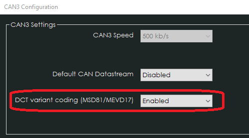
To enable the DCT Variant, Change DCT Variant Coding in CAN3 Configuration to Enabled.
After enabling the setting in CANTCU, the CAN-communication is switched to DCT-type, and you will get fault codes in the DME as it is still expecting auto-trans messages that it has learned to expect. A reset of learned variants needs to be done in the DME to allow learning of the DCT-type messaging. CANTCU (v1.0.138 onwards) will automatically try to reset learned variants when enabling the DCT variant coding. The reset can also be done in INPA through the DME diagnostics, pictured below.
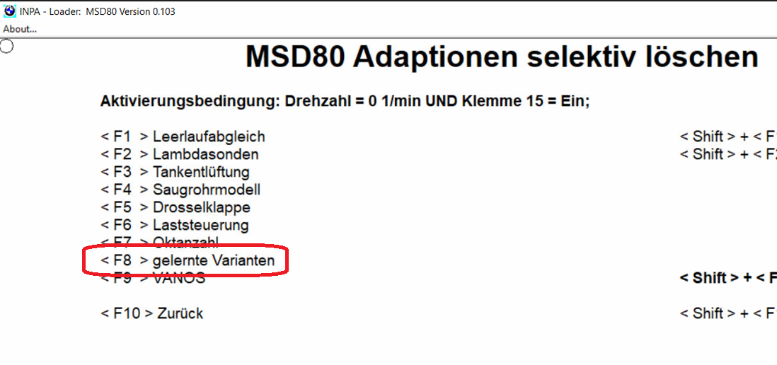
After resetting the variants, fault codes need to be cleared from the DME.
¶ Installation
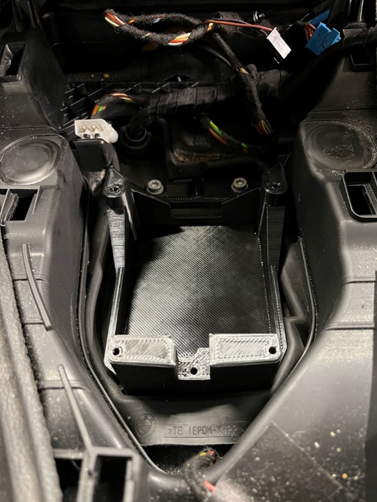
¶ CANTCU Placement
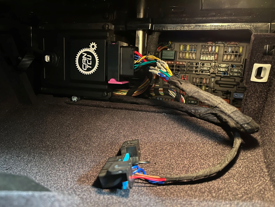
There are several options to mount CANTCU in the car. The two most popular options are the glovebox and ECUbox. Our PnP wiring harness will put CANTCU in the glovebox.
The glovebox is a good place for CANTCU because of easy accessibility.
The ECUbox has the benefit of all the power- and bus-connections being available directly inside it. When installing CANTCU into the ECUbox, it’s recommended to route the USB-cable to inside the car for easy configuration accessibility.
¶ Power Supply
A 15A combined fused power supply for transmission (8HP or DCT), shifter and CANTCU is recommended. This fused power supply is present in the X6021/X6031 connectors inside the ECUbox of all 6HP cars, from where it is routed to the OEM 6HP connector at the transmission. When making your own wiring harness, you can use this power feed directly by repinning the power pins to the 8HP connector instead, or alternatively take advantage of the X6021/X6031 connectors.
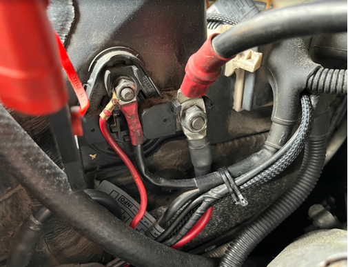
On manual transmission cars which don’t have 6HP wiring harness, and therefore also lack the X6021/X6031 connectors, the power feed for transmission/shifter/CANTCU can be done by using power feed from the jump start pole terminal. Using a 15A fuse, and a relay triggered by ECU power feed, it’s possible to have the transmission powering logic follow OEM ECU/transmission power logic fully. This allows for a proper power-down sequence before cutting the power, which is critical for correct and continuous saving of transmission adaptations.
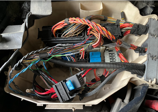
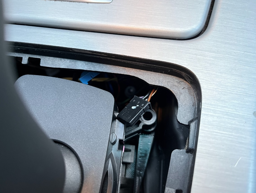
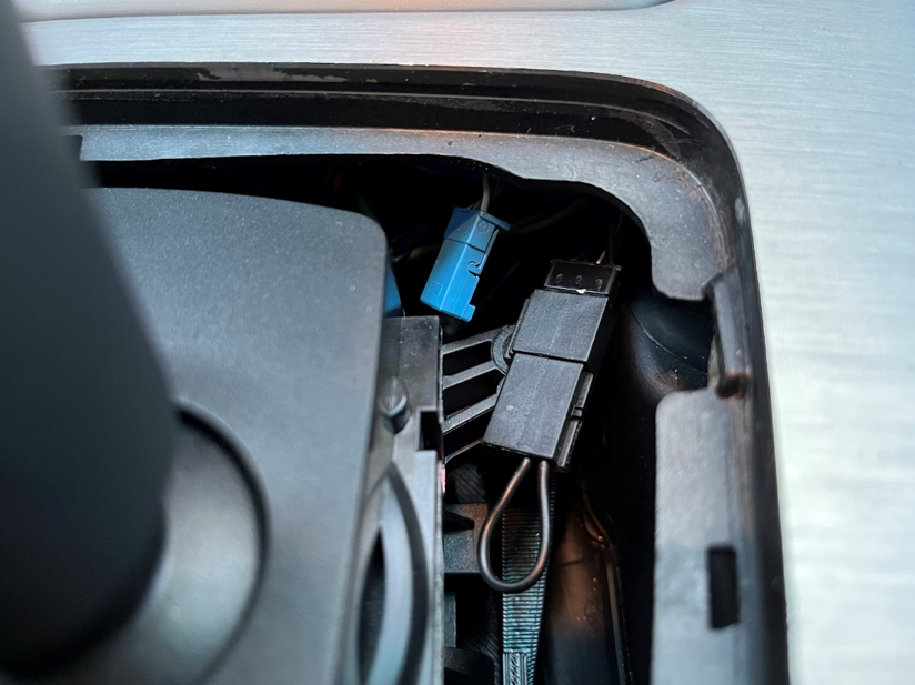
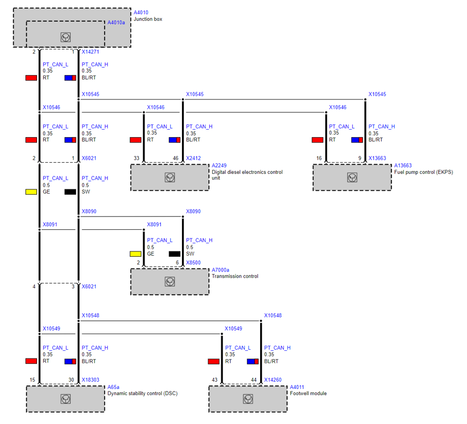
¶ PTCAN-connection
CANTCU CAN3 needs to be connected to the car PTCAN. There are several places to tap into the car PTCAN. It is always available in the ECUbox, and in 6HP cars, it is routed to the X6021/X6031 connectors and looped to the OEM 6HP connector as well. On manual cars, the easiest location to find PTCAN wires, is in the ECUbox at the ECU.
The PTCAN wires can be identified easily because they are arranged as a twisted pair. Wire colors are Red (PTCAN Low) and Blue/Red (PTCAN High). On the 6HP OEM harness (X6021/X6031 connectors) the colors are Yellow (PTCAN Low) and Black (PTCAN High).
¶ Wiring
The wiring usually involves both the inside of the car (Shifter, CANTCU, paddles etc) and the outside (Transmission tunnel, ECUbox etc). The locations for components, and wire routes used, are fully up to the user/installer to decide.
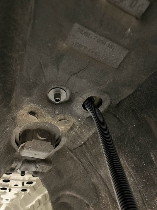
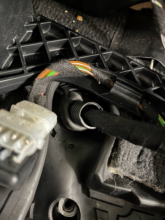
In our experience, the easiest non-intrusive way to route wires between inside and outside the car, is to use the stock shifter cable passage, as the shifter cable will be removed anyways when installing a newer 8HP/DCT transmission.
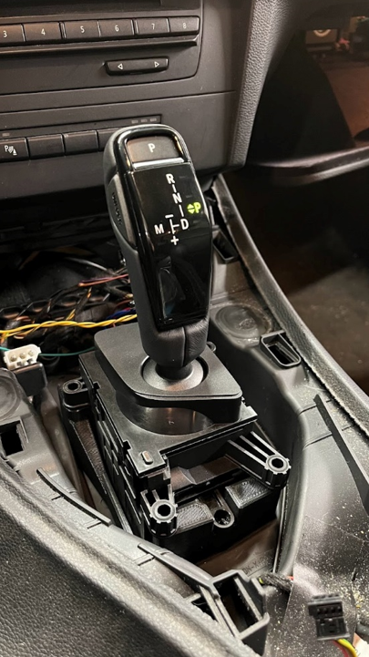
¶ Shifter
CANTCU supports a lot of different shifters, and the list is continuously expanding. Depending on which shifter is going to be used, a shifter adapter might be needed.
- On E6x/7x LCI 6HP cars using the electric “joystick”-shifter, no wiring or modification is needed. The shifter will work directly as it’s already wired to PTCAN. Just select the correct shifter in CANTCU Configurator and you are all set.
- On all other cars, the shifter needs to be wired and connected to either CAN1&2 or CAN3. The connection depends fully on used shifter & transmission combination, valid combinations can be seen at the Supported Shifters page in the wiki.
For the most OEM look and bolt-on installation on E6/7x cars, a LCI model shifter can be used. OEM look and bolt-on installation on E8/9x cars is achieved by using a suitable E8/9x DCT model shifter.
For E8/9x cars, other shifters like F-series 8HP/DCT shifters, G-series shifters and A90 Supra 8HP shifter are commonly used and can easily be fitted to the car using one of our shifter adapters available in the webshop.
¶ Shift Paddles
All different versions of shift paddles are supported. Depending on shift paddle type, the connection to CANTCU is either done by using two Digital Inputs or a single Analog Input and +5Vout.
Pre-LCI “dual function” shift paddles are usually of grounding-type while LCI “single function” paddles are voltage-level dependent.
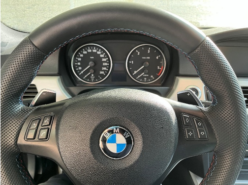
The OEM paddle wires are normally routed through the JBBF module on the E8/9x cars. On E6/7x cars, the wires go directly from the steering wheel to the X6031 connector in the ECUbox. In case of retrofitted paddles, they often are tapped into the stock shifter harness (steptronic switch).
NOTE! Measure the OEM paddle wiring using a multimeter to confirm paddle type before connecting/wiring them to CANTCU. Connecting digital/grounding type paddles on the +5Vout line will cause a short circuit and possible damage to components.
| Model | Model Year | Paddle Type | JBBF (X14271) Pins | X6031 Pins |
| E6x | 2005/09 - 2007/02 | Dual | - | 3 & 4 |
| E6x | 2007/03 - 2007/08 | Dual | - | 10 & 11 |
| E6x | 2007/09+ | Dual | - | 10 & 11 |
| E8x/9x | pre 2006/02 | Dual | - | 3 & 4 |
| E8x/9x | 2006/03 - 2007/02 | Dual | 22 & 38 | 3 & 4 |
| E8x/9x | 2007/03 - 2007/08 | Dual | 22 & 38 | 7 & 8 |
| E8x/9x | 2007/09 - 2008/02 | Dual | 22 & 38 | 7 & 8 |
| E8x/9x | 2008/03+ | Single | 22 & 38 | - |
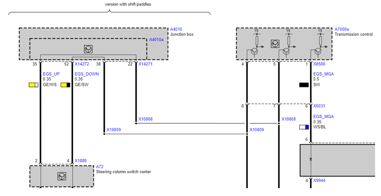
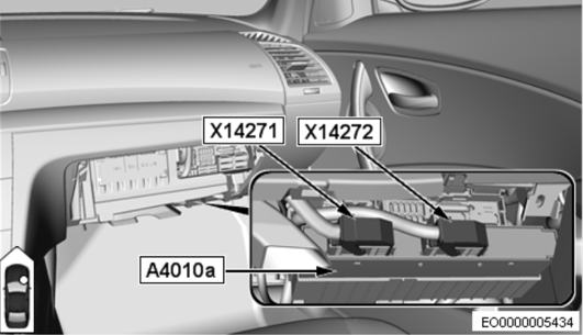
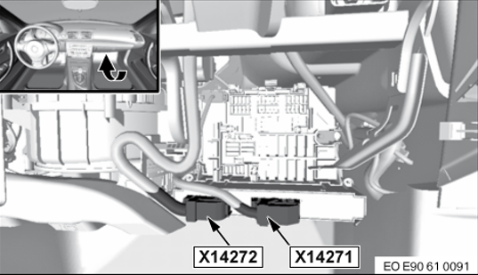
On E8x/9x, we recommend wiring the paddles into the JBBF output connector X14271 if possible. Pins required are of MQS/Quadlock type, identical to the ones used on BMW shifter connectors.
NOTE! Paddle wire colors and pin placements vary through model years. Always check and measure before making any connections.
¶ Programming
If the car was Manual or DCT transmission before the CANTCU installation/transmission swap, programming of the ECU is needed to an Automatic Transmission calibration. This is a requirement because of the type of torque interventions used by CANTCU to command cuts and blips on down/upshifts.
¶ Coding
Coding is a relevant step of the installation as the car needs to be aware of type of transmission used to work properly in all situations. The coding can be done using BMW Standard Tools (NCSExpert) or by any other suitable aftermarket tools that are able to do VO/FA coding and module-specific coding.
NOTE! Coding requires BMW-specific knowledge and software/cables that are outside the scope of CANTCU delivery. If you are unfamiliar with BMW coding, we recommend finding someone experienced do the coding for you.
The coding can be divided into two steps:
- Car needs to be fully coded to an automatic (S205A). If the car was equipped with Automatic Transmission or SAT (Sport Automatic Transmission S2TB) from the factory, this step is unnecessary. If the car was a Manual or DCT Transmission model before the CANTCU installation/swap, this step is mandatory.
- Coding custom parameters in CAS module:
- AUSWERTUNG_P_HW ➝ nicht_aktiv
- ABZUGSPERRE_PLOCK_C6 ➝ nicht_aktiv
¶ PLOCK fault code
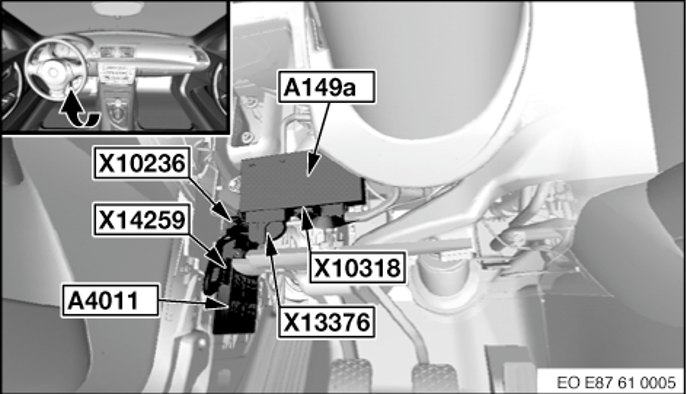
After installation, most cars will throw a CAS fault code related to PLOCK. This fault is rectified by grounding pin 11 on the CAS module. The CAS module is located on the LHD side under the dashboard.
On manual cars, the CAS pin 11 is unoccupied. Wiring will require a MQS/Quadlock pin and some length of wire to be wired to a grounding point nearby.
On automatic cars with a mechanical shifter, the CAS pin 11 is wired to the shifter harness to a black 4-pin connector (X14275). This connector has the PLOCK signal connected on pin 3, and a ground connection is available on pin 4. By making a simple loop wire, the PLOCK signal will be grounded and the fault will be rectified.