
Initial support in v1.1
¶ Features
- Integrates as an “IO 16 Box A or B”
- 5x user-definable inputs/maps into Haltech through free AVIs/SPIs
- Uses values from “Haltech CAN Supported Dash”
- Cut/Blip based on CAN request
- Allows for the use of a Haltech Keypad as shifter
- Haltech Keypad or Rotary Trim Module can be used to select 8HP car drive modes
¶ Connection
CANTCU CAN3 is connected to Haltech 1MB/s CAN-bus.
¶ Torque Factor (CANTCU)
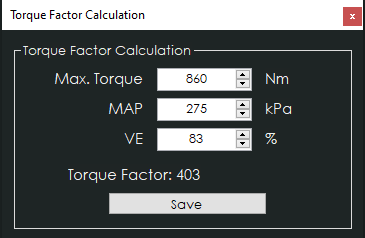
To achieve a somewhat realistic torque estimation, the ECU VE (fuel) table needs to be tuned and show real-world VE-values. For this torque estimation we use a Torque Factor. The torque factor is generated from engine running values taken from a single point of running (usually maximum measured torque on a dyno run). The values needed for calculation are listed below.
- Maximum Engine Torque (Nm)
- Manifold Absolute Pressure, MAP (kPa)
- Volumetric Efficiency, VE, Fuel Table (%)
Entering these values in the calculation window will generate a torque factor, which will be used as a baseline for torque calculations in the CANTCU.
¶ Integration
NOTE!
All tuning should always be done by a professional in safe environment (track/dyno)
Before activating the blip function, it’s recommended to test downshifting and verify (realtime or logging) that the user table is behaving correctly during the blip. Starting values for tuning the blip should be low and gradually increased to avoid overrevving and undesired behavior/acceleration during the shift.
¶ Haltech Configuration
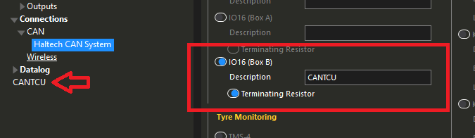
- Under Haltech CAN System, IO16 Box A or Box B needs to be activated depending on which one you have selected in CANTCU configuration. Both have identical functionalities. After selection, the unit will appear in the tree listing (red arrow).
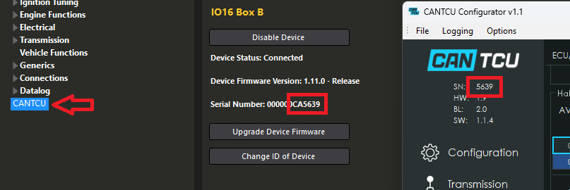
- The "CANTCU" IO16 -selection will show the CANTCU serial number with a “CA”-prefix to not confuse it with a Haltech IO16 expander unit.
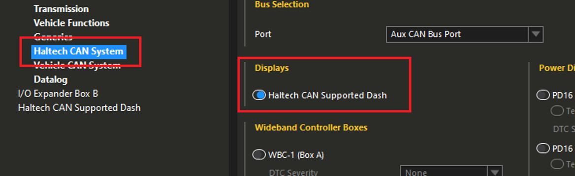
- Under Haltech CAN System, Haltech CAN Supported Dash needs to be activated.
- For CANTCU torque calculations, a Generic Output sending Base Fuel Tuning on IO16 output DPO1 needs to be defined. The variable needs to be scaled down to fit into the 0-100% duty cycle range of the DPO.
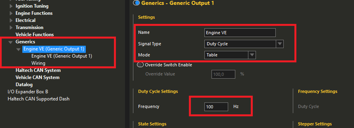
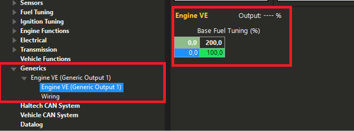
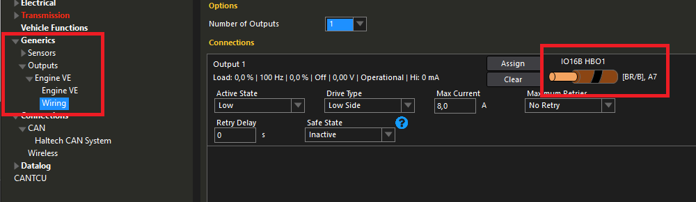
Available Realtime-values in CANTCU (sent from Haltech):
| Engine RPM |
| TPS Value |
| Engine MAP |
| Wheel Speeds |
| Brake Switch |
| Coolant Temperature |
| Engine Oil Temperature |
Available Realtime-values in Haltech (sent from CANTCU):
| Gearbox Gear |
| Gearbox Mode |
| Gearbox Oil Temperature |
| Gearbox Cut % Request |
| Gearbox Blip % Request |
| Cut trigger |
| Blip trigger |
| Rate | Realtime variable | Input name | Unit | Conversion |
| 50 Hz | TCU Gear | AVI1 Voltage |
0-4.5V |
|
| 50 Hz | TCU Oil Temp | AVI2 Voltage |
C |
min -40 max 160, 0-5V |
| 50 Hz | Cut/Blip Trigger | AVI3 Voltage |
0/1/2 |
1/2.5/4V |
| 50 Hz | TCU Cut % | SPI1 Duty Cycle |
% |
0-5V = 0-100% |
| 50 Hz | TCU Blip % | SPI2 Duty Cycle |
% |
0-5V = 0-100% |
¶ I/O Configuration
To be able to control cuts and blips, functions like Gear Ratio, Shift Request and Flat Shift are enabled under Transmission in Haltech.
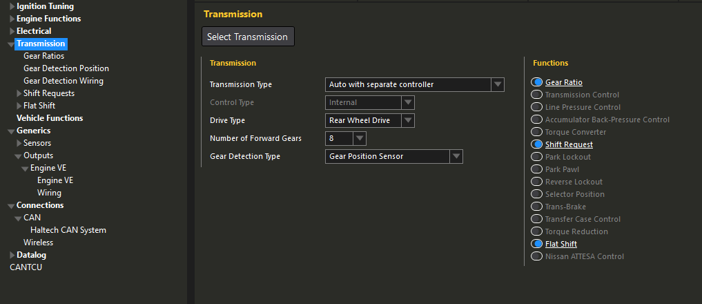
Gear Ratios need to be calibrated while driving.
Gear Detection Position is defined as following:
|
Gear |
1st |
2nd |
3rd |
4th |
5th |
6th |
7th |
8th |
Reverse |
Neutral |
|
Voltage |
1.2 |
1.6 |
2.0 |
2.4 |
2.8 |
3.2 |
3.6 |
4.0 |
0.4 |
0.8 |
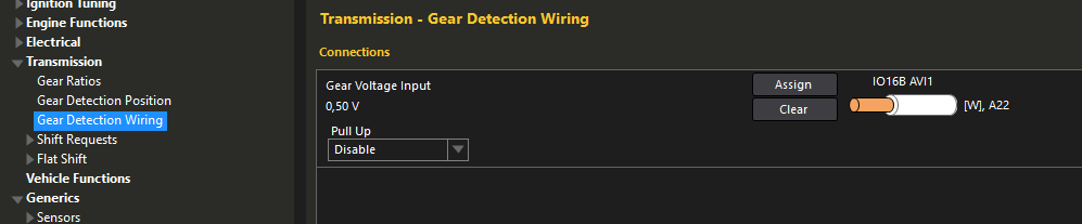
Gear Detection Wiring is defined to IO16 AVI1.
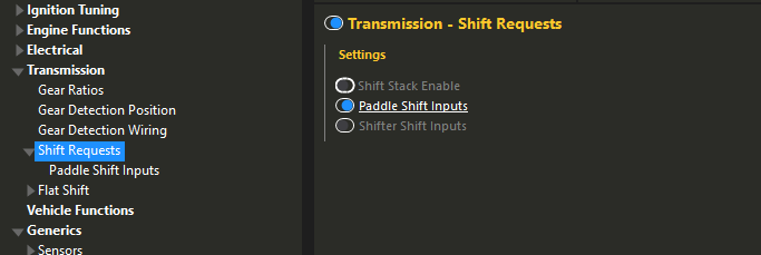
Shift Requests has Paddle Shift Inputs enabled to allow up/downshift triggers from CANTCU.
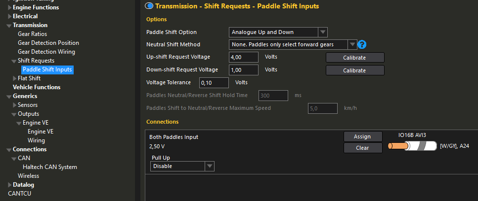
Paddle Shift Input uses both ”Up” and ”Down Paddles” that are assigned to IO16 AVI3.
¶ Cuts and Blips
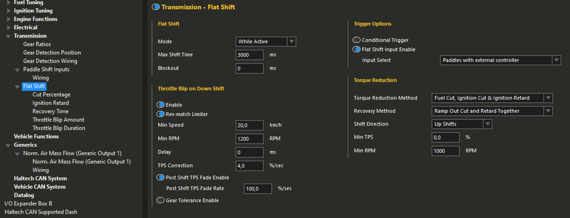
The Flat Shift function dictates how both cuts and blips are performed. Flat Shift mode needs to be ”while active”, to let CANTCU decide the length of cuts. Triggering of the function is done by the virtual paddles that are defined on the IO16 DPIs. The method of cutting (listed under Torque Reduction) can freely be chosen to whatever suits engine setup and driving style. Shift Direction on torque reduction needs to be ”up shifts” only, as the paddle signal sent from CANTCU is a cut request. Blips are enabled and use the downshift paddle as a trigger. A rev-match limiter is used to keep the RPM’s from overshooting until the blip is done.
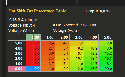
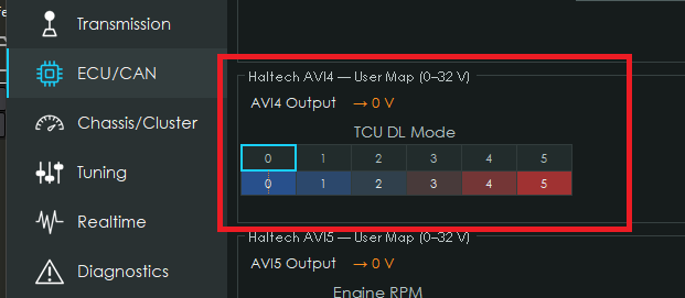
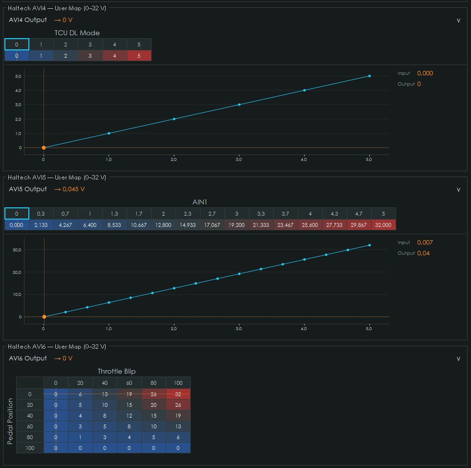
For cuts, both the Cut Percentage and Ignition Retard maps will use IO16 SPI1 (Cut% from CANTCU) as an axis. This way the cut intensity can be fully controlled and adjusted during the shift. Other axes can be freely defined. An example of this is shown below using IO16 AVI4 (mapped in CANTCU to broadcast DCT DriveLogic Mode) as an added Y-axis for different behavior of the flat shift cut function depending on transmission drive mode.
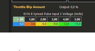
For blips, Throttle Blip Amount and Throttle Blip Duration tables are used. The Throttle Blip Amount table uses IO16 SPI2 (CANTCU Blip %) as an axis to modulate the DBW throttle target during the blip. The Throttle Blip Duration table defines the length of the blip depending on user-definable axes.
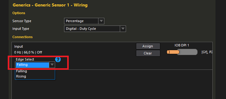
NOTE! SPI Percentage values are always sent as “Falling” trigger mode. If you are seeing inverted percentages (66→0% in CANTCU resulting in 33→100% in Haltech), you need to change the trigger edge. You can do this by temporarily assigning the SPI to a generic sensor and change the trigger edge.
¶ Extra Values
The IO16-integration allows us to have free user-definable inputs, 3 AVIs and 2 SPIs, from CANTCU sent to Haltech. The input signals can be freely defined in CANTCU to send over drive modes, extra values like slip percentages, shaft RPMs, parameters that help with cutting/blipping etc or extra sensors through CANTCU analog inputs. Some examples below.
¶ CANTCU DOUT triggering through Haltech
The IO16 -configuration that serves as a base for CANTCU-Haltech integration, allows Haltech to control the CANTCU Digital Outputs (On/Off).
NOTE! The available frequency range is 10-1000 Hz.
| Haltech | CANTCU |
|---|---|
| IO16 DPO1 | Used by VE Output |
| IO16 DPO2 | Not Used |
| IO16 DPO3 | DOUT1 |
| IO16 DPO4 | DOUT2 |
| IO16 DPO5 | DOUT3 |
| IO16 DPO6 | DOUT4 |
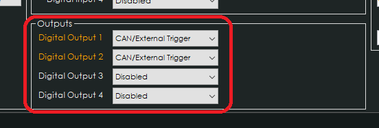
In CANTCU, the used DOUT(s) need to be configured as “CAN/External Trigger”.
¶ 8HP Car Drive / DCT DriveLogic Mode from Haltech Keypad or Rotary Trim Module
When using a Haltech Keypad, you can create a virtual Rotary Trim Module and assign it to a Haltech Keypad button, allowing the different 8HP car drive modes to be selected. Note that even though the instructions are for a “virtual” Trim Module through the Haltech Keypad, you can also use a Rotary Trim Module directly. There also are a lot of ways to set everything up according to user preference, our instructions serve as a guide/example of what's possible.
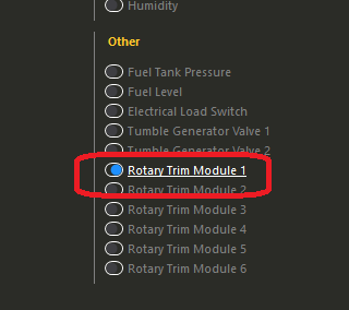
Start by enabling a Rotary Trim Module in the Sensors -menu. Trim modules 1-3 are supported (and routed to CANTCU).
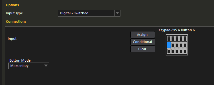
In the Rotary Trim Module Wiring -menu, select the input type as Digital - Switched and assign it to a Haltech Keypad button. The Button Mode should be set as Momentary to avoid having to double press for every step. If you're using a real Rotary Trim Module, assign it to the input you've wired the Trim Module to.
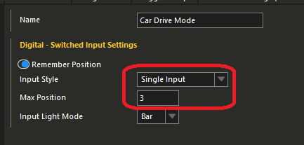
Give the Rotary Trim Module a suitable name of your choice and configure the general behavior of the button. The Input Style needs to be Single Input and Max position 3 (8HP & F-DCT) or 6 (E-DCT) other settings such as remembering the position and Light modes can be freely selected by user preference.
In CANTCU, you need to activate the corresponding Rotary Trim Module (1-3) based on which one you decided to use in Haltech.
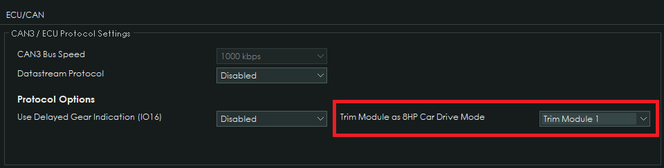
All done! The 8HP Car Drive Mode (or DCT DriveLogic Mode) will now change between the modes according to the Rotary Trim Module Position. The position is indicated on the Haltech Keypad by LEDs.
¶ 8HP
| Position | 8HP Car Drive Mode | Keypad Button LEDs |
| 0 | ECO Pro | Off |
| 1 | Comfort | 1 |
| 2 | Sport | 2 |
| 3 | Sport+ | 3 |
¶ E-DCT
| Position | DCT DriveLogic Mode |
| 0 | - |
| 1 | DriveLogic 1 |
| 2 | DriveLogic 2 |
| 3 | DriveLogic 3 |
| 4 | DriveLogic 4 |
| 5 | DriveLogic 5 |
| 6 | DriveLogic 6 |
¶ F-DCT
| Position | DCT DriveLogic Mode |
| 0 | - |
| 1 | DriveLogic 1 |
| 2 | DriveLogic 2 |
| 3 | DriveLogic 3 |