Thank you for choosing CANTCU! We have compiled a step-by-step guide for you to follow through your build. Below you will find everything you need to get you through the installation and start driving! If you encounter any problems, check out our Troubleshooting page. If the troubleshooting guide doesn’t give you the answers you are looking for, feel free to ask for help in the CANTCU Community (Facebook Page), or contact us directly at support@canformance.net.
¶ 1. Installation and Wiring
Every installation is unique, but the basic steps remain the same. You can find all the needed information and schematics for the basic installation in our wiki-pages
¶ Transmission installation
- BMW 8HP 1st Gen F-Series
- BMW 8HP 2nd Gen F-Series
- BMW 8HP 2nd Gen G-Series
- BMW 8HP 3rd Gen G-Series
- BMW DCT E-Series
- BMW DCT F-Series
Depending on which type of shifter you will be using, you need to also adapt the wiring accordingly. A lot of different shifters are supported, most of them connected via CAN-bus, but some also to Digital Inputs. The full list of supported shifters and their pinouts can be found at the link below:
Various paddles (analog/digital) and other supported devices like steering wheel buttons can be found in the link below:
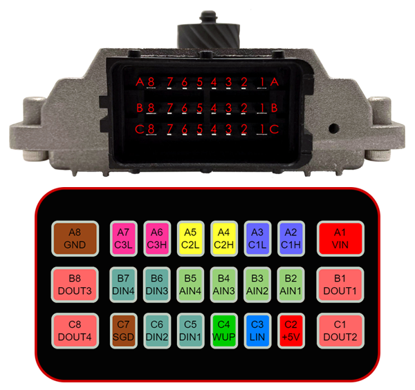
For any extra I/O wired into CANTCU, check out the CANTCU Pinout page to have a clear view of the connector pin layout.
¶ CANTCU Connector pinning
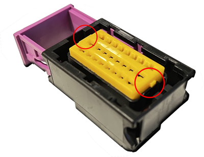
To install pins into the connector housing, start by lifting the yellow “lock plate” inside the housing by carefully by prying the side tabs open using a suitable tool. You can also completely remove the lock plate. Be careful not to bend/snap the side tabs.
With the lock plate lifted, insert pins into correct slots on the housing and press them through the insulation rubber until they seat and lock inside the connector housing. After all necessary pins have been inserted, reinstall/secure the lock plate by pressing it in fully.
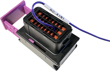
The example picture below shows AIN1 wire installed to B2 on the connector housing.
¶ CAN-bus Wiring
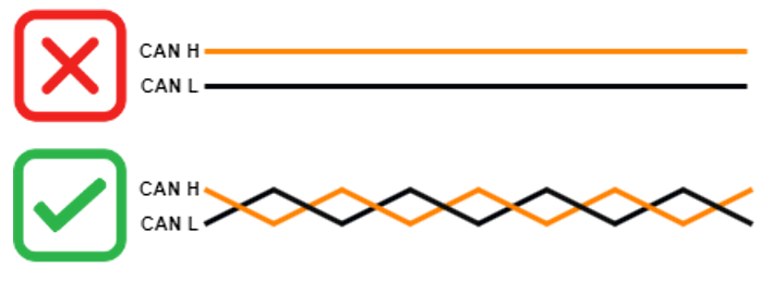
The CAN-bus is an information data bus used in the automotive sector, in which data is transferred using copper conductors (wires). The copper conductors are wired between all the different nodes (control units) in the bus. The bus physically consists of two conductors (wires), CAN H (High) and CAN L (Low), which are arranged in a twisted-pair configuration. The twisted-pair arrangement of the conductors is a requirement, as it plays a critical part of noise cancellation, affecting signal quality.
¶ Topology
In the CAN-bus, every node is a master device. This means that every node has the equal rights and possibility to send and receive all the messages available on the CAN-bus. It is up to the configuration/software of every node to decide which CAN-messages are received and further processed in the node. An ideal CAN-bus layout consists of a main bus, terminated at both ends using 120 ohm resistors, resulting in a bus resistance of 60 ohm. Devices are spliced into the bus. The maximum recommended lengths of both the main bus and device stub vary depending on bus speed.
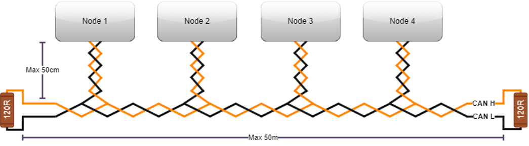
Due to physical limitations, it is often impossible to achieve a fully ideal CAN-bus layout, especially regarding stub lengths. Thankfully, CAN-bus is not too sensitive about this and will usually work fully normally even when outside the specified lengths.
¶ Termination resistors
A CAN-bus is always required to have a resistance of 60 ohms. This resistance is achieved by using two 120 ohm resistors placed at the ends of the CAN-bus, hence called Termination Resistors. The main purpose of these resistors is to absorb energy created by the CAN signals. Without resistors at the ends of the CAN-bus, there is a risk of the CAN signals reflecting back from the end of the bus cables, which could result in communication errors or even total loss of communication. Regarding resistor wattage, a standard 1/4W (0.25W) resistor is adequate and easy to wire in. A lot of OEM, and even aftermarket ECUs, have built-in termination resistors. On OEM, this usually depends on the placement in the car. Aftermarket ECUs sometime have a software-activated termination resistor. This is something that needs to be taken into consideration when planning the wiring harness and/or before adding any resistors to an existing CAN-bus.
CANTCU has built-in 120 ohm resistors on CAN1 and CAN2, and is supplied with 4x 120 ohm resistors to be wired in where necessary.
| CAN-bus | Termination Resistor |
| CAN1 | X |
| CAN2 | X |
| CAN3 | - |
¶ Measuring resistance
Use a suitable multimeter with a resistance-measurement (ohm) function. Before measuring resistance, make sure that all devices are connected to the CAN-bus, and that all devices are powered OFF.
| Bus Reading | Explanation | Solution |
| 0 ohm | Short in wiring | Fix CAN wiring |
| 60 ohm | Bus terminated correctly | - |
| 120 ohm | Only one termination resistor on the bus | Add another termination resistor on the opposite end of the bus |
| Infinite ohm | No termination resistors on the bus | Add termination resistors to both ends of the bus |
¶ Practical Guidelines
- Use twisted-pair conductors/wiring
- Make sure the total resistance of the CAN-bus is 60 ohm
- Keep device stubs as short as possible
¶ 8HP/DCT Connector
The 8HP/DCT connector consists of a center portion and a sleeve lock. The connector is normally supplied with the center portion in a position that allows easy pinning of the wires. After all the necessary wires have been inserted, the connector center portion needs to be pushed out and locked in place. If the connector center portion isn’t pushed out, the pins will not engage the transmission pins.
¶ 2. Integration
Different ECU/cars need different ways of communicating with CANTCU. That’s why we don’t generally use a “universal” connection, but rather predefined presets for every ECU we choose to support. This way it’s easy for You to just configure everything the way Your ECU works best. Choose your ECU/car from the table below to find out how to install and configure everything. If your ECU doesn’t have instructions available yet, please send us an email to support@canformance.net to get assistance.
The detailed list of supported ECUs can be found on the Supported ECUs page.
¶ 3. Configuration Software (PC)
After everything is wired up, you are ready to start configuring CANTCU. For configuration the PC software CANTCU Configurator is used. The latest version is available in the wiki.
¶ 4. Transmission software unlocking
Depending on transmission used, either an immobilizer reset or custom software flash usually is mandatory. Immobilizer reset (8HP) is done using CANTCU Flasher integrated in the PC software (CANTCU Configurator). Some (non-BMW) transmissions need an initial bench flash to convert to suitable BMW-based software. See table below for options for different transmissions.
| Integration | Designation | Transmissions | Immo Reset/Custom Software | Flash Procedure |
|---|---|---|---|---|
| BMW DCT F-Series | GS7D36SG | BMW M2/M3/M4 | Immo Reset | CANTCU Flasher |
| BMW DCT F-Series | GS7D70SG | BMW M5/M6 | Immo Reset | CANTCU Flasher |
| BMW 8HP F-Series 1st Gen | 8HP45 / 70 / 90 | All Gasoline/Diesel cars | Immo Reset | CANTCU Flasher |
| BMW 8HP F-Series 2nd Gen | 8HP50 / 75 / 95 | All Gasoline/Diesel cars | Immo Reset | CANTCU Flasher |
| BMW DCT E-Series | GS7D36SG | BMW 135/335/Z4 35 and M3 | Custom Software | BMW Tools (1*) |
| BMW 8HP G-Series 2nd Gen | 8HP50 / 75 / 95 | All Gasoline/Diesel cars | Immo Reset | CANTCU Flasher |
| BMW 8HP G-Series 3rd Gen | 8HP51 / 76 | All Gasoline/Diesel cars | Immo Reset/Bypass | 3rd Party (2*) |
| BMW 8HP E-Series | 8HP45 / 70 | E70/E84 | Custom Software | Bench Flash (3*) |
| BMW 6HP E-Series Mech | 6HP19 / 26 | Exx Cars, Mechanical Shifter | - | - |
| BMW 6HP E-Series CAN | 6HP21 / 28 | Exx Cars, Joystick Shifter | - | - |
| Dodge 8HP 1st Gen | 8HP45 / 70 | All Gasoline/Diesel cars | Custom Software | Bench Flash (3*) |
| Jaguar 8HP 1st Gen | 8HP45 / 70 | All Gasoline/Diesel cars | Custom Software | Bench Flash (3*) |
| Land Rover 8HP 1st Gen | 8HP45 / 70 | All Gasoline/Diesel cars | Custom Software | Bench Flash (3*) |
- 1* : A BMW KDCAN-cable and BMW Standard Tools / WinKFP + a full version of SP-Daten needs to be installed locally. The aforementioned software can be provided by us upon request. Flashing takes place during a remote session, in which we install the custom software.
- 2* : Immobilizer needs to be reset or bypassed by a suitable 3rd party flash option. Support will be added to CANTCU Flasher in the future.
- 3* : An initial full flash is needed to convert the transmission software to suit CANTCU usage. Yanhua Mini ACDP or similar tool for the SH7254xx processor can be used. The TCM can be shipped in to us or a capable reseller for this procedure.
Flashing with CANTCU Flasher is done through the CANTCU USB port. CANTCU Flasher supports most of the supported transmissions, and gives you options to customize the transmission functions.
Alternatively, if your transmission (E-series DCT) needs a remote session for flashing custom software, please follow the instructions below.
¶ 5. Test Drive
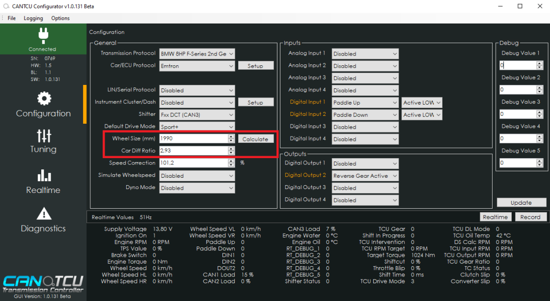
After configuring everything according to the ECU-specific requirements and adjusting the basic parameters like wheel size/diff ratio etc in the configuration software, you should be all set to test for wheel movement. Before setting off, we recommend that you check and verify that the following Realtime-values in CANTCU Configurator show accurate values:
- Engine RPM
- Pedal Position
- Brake Switch
- Wheel Speed
- Engine Torque (at speeds over 15km/h)
- Engine MAP (if used/visible)
- TCU Gear
- TCU Oil Temp
If all values are accurate, the next step is to check that gears are engaging and wheels are moving. We recommend performing the initial tests with the vehicle/driven wheels in the air. If gears engage, but immediately or occasionally go back to P, the oil level is too low and needs to be adjusted/filled.
With successful engagement of gears and rotation of wheels, you are almost set. To get the best possible operation, it is important to calibrate the differential ratio to show correct values, this way the transmission stays happy with the speed information it is getting, regardless of used differential ratio. You can perform the differential ratio calibration either while driving or on a lift. The higher the speed, the more precise the calibration will be. At minimum a speed of 50km/h is recommended to achieve a good calibration.
¶ Differential Calibration - 8HP
NOTE: On 8HP transmissions, when using a transfer case with high/low ratios, it is mandatory to use Simulated Wheelspeed in CANTCU as the total gear ratio between the output shaft and rear wheels are changing, confusing the transmission when it has learned a static ratio.
1. Open CANTCU Configurator and verify correct Wheel Size and Differential Ratio in the Configuration-section. The diff ratio parameter needs to match one of the predefined ratios in the transmission software listed below. If your car diff ratio is not listed, please use the closest matching one.
| 2.35 | 2.47 | 2.56 | 2.81 | 3.08 | 3.15 | 3.23 | 3.38 | 3.46 | 3.64 | 3.73 | 3.91 | 4.10 | 4.27 |
2. Drive the car and follow Realtime-values TCU Output RPM and DS Calc RPM. If you are unable to watch the values during driving, you can record a log and stop to check values afterwards.
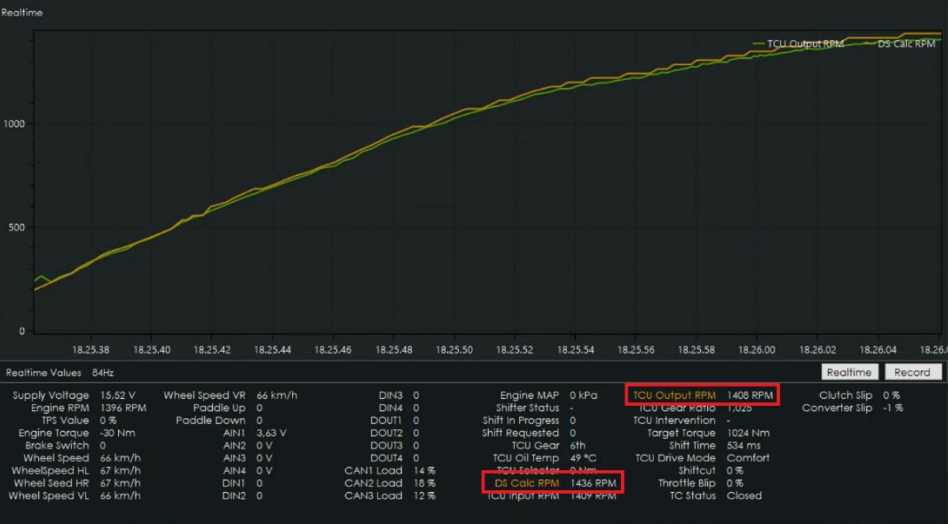
3. If the difference of the two aforementioned values is greater than 15 RPM at decent speed (>50km/h), you need to adjust the Speed Correction factor (in Configuration-section).
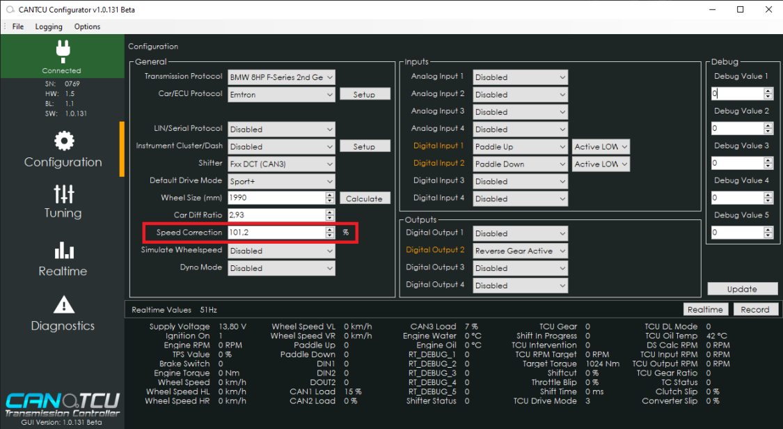
I. DS Calc RPM < TCU Output RPM → Decrease Speed Correction factor
II. DS Calc RPM > TCU Output RPM → Increase Speed Correction factor
Adjust the Speed Correction factor using 1-2% increments until you are close, then fine tune using 0.1% increments.
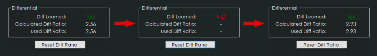
4. After a properly adjusted Differential Ratio Calibration, the learned differential ratio needs to be reset and relearned. In the Diagnostics-section, perform a information Read to check the current learned differential ratio. If it is not matching with real differential ratio, click Reset Diff Ratio. Then perform a new calibration by driving normally until the correct ratio has been fully relearned. The relearn status can be checked by clicking on the Read button again.
¶ Differential Calibration - DCT
1. Open CANTCU Configurator and verify correct Wheel Size and Differential Ratio in the Configuration-section.
2. Drive the car using 1:1 gear ratio (5th gear on F-DCT, 7th gear on E-DCT) and follow Realtime-values TCU Output RPM and Engine RPM. If you are unable to watch the values during driving, you can record a log and stop to check values afterwards. If the difference of the two aforementioned values is greater than 15 RPM at decent speed (>50km/h), you need to adjust the Speed Correction factor (in Configuration-section).
I. Engine RPM < TCU Output RPM → Decrease Speed Correction factor
II. Engine RPM > TCU Output RPM → Increase Speed Correction factor
Adjust the Speed Correction factor using 1-2% increments until you are close, then fine tune using 0.1% increments.
NOTE: If you experience inaccurate TCU Target RPM requests while shifting after a successful calibration, please make sure you have the correct differential ratio flashed to the transmission.
¶ 6. Tuning
Generally, zero to minimal tuning in CANTCU software is required, but depending on ECU integration there might be some configurable parameters. Those parameters are found on the Tuning page in CANTCU Configurator software, and explained on the matching ECU integration page.
Depending on used ECU integration, cuts and blips need to be dialed in for correct and best functionality. OEM integrations usually don’t require this, while Standalone ECUs do. Please refer to the ECU integration pages in for detailed information on what and how to tune your specific ECU integration.
The possibility to modify transmission behavior like RPM limits, shiftmaps and more depends on transmission used, see the CANTCU Flasher page for more information.